Continue to Site

Welcome to EDAboard.com

Welcome to our site! EDAboard.com is an international Electronics Discussion Forum focused on EDA software, circuits, schematics, books, theory, papers, asic, pld, 8051, DSP, Network, RF, Analog Design, PCB, Service Manuals... and a whole lot more! To participate you need to register. Registration is free. Click here to register now.

3 phase 400Vac 5000W Full bridge converter power factor correction Buck or Boost type

Status
Not open for further replies.
What do you think about the boost topology?
Boost topologies have been suggest previously in this thread. I understand that your bias towards separate single-phase PFC units is related to predesigned solutions from TI. Industry standard solutions are three phase PFC converters like Vienna rectifier or bidirectional active front end.

- - - Updated - - -

I don't agree that "synchronise with the AC-line" is the key point for different topologies. It's more generally the ability to sink a sinusoidal current independently in each phase. It's e.g. not possible if the mains current is routed through a three-phase bridge.

The 3 phase rectifier bridge is really a non reversable function. I added just a plain resistive load after the 3 phase B6 rectifier bridge. I then measured each phase current seperatly. The results obeys that the rectifier bridge is really a headache for the power factor.

Even a simple resistive load after the bridge has neither a good PF nor a good crest factor.

Converter-bridge-ResistiveLoad.png

Converter-bridge-ResistiveLoad-scheme.png

I am now trying to simulate what happens if this resistance changes its value sinusoidially. I think even then the PF and crest factor will be bad. As you said the most convenient way is to control the bridge directly. Because after the bridge we are in such a world that a mathematically reverse transform is really hard.


Interestingly , on TI forum there are developers claiming to use one stage TI controllers after the 3 phase B6 rectifier bridge. I am confused because even if the IC develops a sinus form input current, it is really another story how the phase currents look like at each phase before the rectifier.
 
Last edited:

Interestingly , on TI forum there are developers claiming to use one stage TI controllers after the 3 phase B6 rectifier bridge. I am confused because even if the IC develops a sinus form input current, it is really another story how the phase currents look like at each phase before the rectifier.
You are right, it's impossible to achieve sinusoidal input current through B6 bridge. But you can achieve 120° conduction angle with arbitrary waveform, similar to a buck PFC with 2:1 voltage ratio.
 
  • Like
Reactions: rxpu

    rxpu

    Points: 2
    Helpful Answer Positive Rating
The rectified output is (in a manner of speaking) two split (bipolar) supplies. Together they create a voltage doubler to the 5kW load.

Then as seen in your post #22, the graph of raw Ampere output has 'funny bumps'. The waveform is out of alignment with the voltage waveform (power factor error).

The LC second order filter is suitable to shape the waveform. I tried adding two filters, one at the positive output and one at the negative. By playing with values we can improve power factor. There is a point where changing either L or C causes a surprisingly large shift of the Ampere waveform toward leading or lagging.

3-phase 230VAC wye 6 diodes (2L 2C pfc) load 650vDC.png

The righthand scope trace plots AC supply V versus A. Notice it is symmetrical, indicating the Ampere waveform is centered on the voltage waveform. It is an improvement over a lone inductive filter or lone capacitor filter.

- - - Updated - - -

C3 is disconnected in the screenshot but if it is installed then output voltage can (theoretically) rise to smooth 620 VDC at 5kW to the 75 ohm load.
 
  • Like
Reactions: rxpu

    rxpu

    Points: 2
    Helpful Answer Positive Rating
You really need a buck-boost input topology for good power factor from rectified two phase or single phase mains, else the buck is ineffective when Vin(instantaneous) < Vout.

A buck boost can be a buck converter followed by a boost, or you can add the extra bits around the buck choke to make it boost as well.

There are control chips avail for this.

Also Cuk converter - if you are experienced at the 1700W module level ...

good luck

Buck-boost should be a 2 stage converter. Each stage will add power loss. You will get better PFC but you give away more than what you earn.

Do you think that boost topology will not be enough?. 230Vac Rectified : 328Vdc Boost voltage : 370Vdc

Is 40V not enough for a good PF margin?
 

If you draw it out - a buck boost only has one inductor, and one active switching power semi in ckt at any one time - hence not two converters in series, the boost stage always has the o/p diode in series and and the buck part will have the series pass element fully on when boosting - it is the most elegant solution for a number of reasons - most especially because you can set the Vo lower than for the peak Vin.

Sure you can boost to 385VDC or similar for single phase - but if you read the thread - OP was seeking two phase input for 3 modules, 400 phase - phase - this is ~ 600V peak so you would have to boost to 650 VDC at least ...

I examined the Cuk converter. It has a series high voltage capacitor which may increase the cost. But anyhow why I get away from the buck topoplogy is: The switch is in series with the line. This may lower the robustness of the system and is prone to lightining strikes , load dumps. etc. There is too much stress on the buck switch which may reduce reliability especially for industrial supply networks.

I seperated the converter into 3 seperate phase to phase rectifiers. It was the idea that I do not use the neutral line. Only 3 phases and the system balances its own neutral line. But then I changed this scheme to 3 seperate B4 rectifiers with the neutral line. Because the line voltage will be much less and I can work with lower Voltages (370VDC instead of 600VDC) for the boost output voltage.

My input voltage range is narrow. for 230Vac rectified , it is between 280Vdc and 320VDC. So the for a buck converter is also eliminated.

It would be better if I would eliminate the neutral line at the input. But as you said the boost voltage without neutral line is 600Vdc.

I preferred to use the rectification between neutral line and the phase to lower the input voltage for the boost converter.

Is it a good compromise? Or do you think that a 3 phase input without a netral line is more robust and should not be sacrificed.
 

In most western industry running a neutral line is a hassle - but can be done. I note your concern with the buck switch - the best way around this is to have your down converter able to withstand up to 800V and turn the down converter off if the volts from the PFC stage go higher than design regulation ( e.g. 400V ) when running off two phases. Just remember you can't join the 0v lines if you take each pair of phases and then run them through 3 bridge rectifiers ....
 

Just remember you can't join the 0v lines if you take each pair of phases and then run them through 3 bridge rectifiers ....

I found a solution to this problem: Each phase has its own full bridge conveter with *isolated transformer*. I combine the outputs of the isolated transformers. With this method I can combine the outputs of each phase to each other.

I also gain the 300Hz ripple again that I lost by seperating the rectifiers each having 50Hzx2=100Hz, at the combined output. Because each seperated 100HZ is 120 degree phase shifted. When combined at the output I gain the 300Hz ripple again.

What do you think abaout it?
 

The threefold single phase solution has been already discussed at the begin of this thread. It's feasible but has some disadvantages. E.g. the energy storage of the single phase converters has to be designed for 100 Hz ripple. Three phase PFC has virtually no output ripple (not even 300 Hz), three phase sinusoidal current corresponds to continuous energy flow.
 

3 x single phase does have the advantage of relative simplicity - a 6 diode bridge has to be followed by a DCM boost stage for good power factor ... but is also simple - drawback being very high peak currents ...
 

It should be possible run each PFC as a flyback converter by adding a secondary winding to the PFC inductors. This can be designed for 10 VDC output, which means that the high-voltage DC bus is eliminated completely.
Each converter has it's own synchronous rectifier, but they can share the 10V DC bus (= the output voltage). The 10 V DC should have the 3-phase advantage of no ripple.
 

the peak currents in each of the 1700W flybacks would be problematic, and what about the turn off volts on the pri switch ...? also the cores would be quite large ...
 

the peak currents in each of the 1700W flybacks would be problematic, and what about the turn off volts on the pri switch ...? also the cores would be quite large ...

At first I designed each 1700W converter as full bridge phase shift converter. Then I changed my scheme to an LLC converter. (the secondary output stress on synchronous rectifiers are better).

The regulation loop of the LLC stage is so designed that (slow regulation ,very high phase margin) there will be no peak currents.

Each converter has its own current shunt and has its own closed loop control. A host controller adjusts the current and voltage set points and sends the commands to the slaves. The slaves regulate independantly their own current and the voltage. Slaves have current limit for voltage control, and for pure current control a voltage limitation routine.

This will ensure that all slaves can be paraleled even if it is a common idea that paralelinng LLC converters is a bad idea.

- - - Updated - - -

It should be possible run each PFC as a flyback converter by adding a secondary winding to the PFC inductors. This can be designed for 10 VDC output, which means that the high-voltage DC bus is eliminated completely.
Each converter has it's own synchronous rectifier, but they can share the 10V DC bus (= the output voltage). The 10 V DC should have the 3-phase advantage of no ripple.

Flyback converter has some disadvantages. Weak core utilization and bad EMI. I prefer an LLC converter with its own current shunt and its own closed loop control for current and voltage so that a paralell connection of 3 seperate LLC converters is possible.

What do you think abaout it?

- - - Updated - - -

The threefold single phase solution has been already discussed at the begin of this thread. It's feasible but has some disadvantages. E.g. the energy storage of the single phase converters has to be designed for 100 Hz ripple. Three phase PFC has virtually no output ripple (not even 300 Hz), three phase sinusoidal current corresponds to continuous energy flow.

If we combine the outputs of each converter, we should gain the 300Hz ripple again?. Isnt it?

If each converter has 100Hz at 120 degree phase shift, combining the output of each converter superposition these low frequency 100Hz to a 300Hz at the output of the isolated transformers.

This would also mean that energy storage capacitors are better utilised. (Or can be a lower value just as in 3 phase rectifier).
 

This would also mean that energy storage capacitors are better utilised. (Or can be a lower value just as in 3 phase rectifier).

No. Without energy storage, each single phase converter has output current swinging between 0 and 2*Iavg. You can either implement energy storage sufficient for 100 Hz ripple in front of each DC/DC converter, or need to design the DC/DC for 2*Iavg peak current, as discussed before.
 

No. Without energy storage, each single phase converter has output current swinging between 0 and 2*Iavg. You can either implement energy storage sufficient for 100 Hz ripple in front of each DC/DC converter, or need to design the DC/DC for 2*Iavg peak current, as discussed before.

The capacitor cost is not to dramatic. For 1700W and 360VDC Voltage, a 660uF 400V should be sufficient. It costs (2x330uF) abaout 3$ in total.
I know that the input capacitor is a little bit underdimensioned. but I trust the superposition of 3 seperate 120 degree phase shifted 100Hz ripple at the output. The voltage ripple at each converter output will compensate each other at the combined output. But as you said with a little underdimensioned 660 uF capacitor the converter must be dimensioned for 1.2-1.3xIavg peak current.
 

I don't know what's sufficient for x1.3 peak current, depends on the DC/DC stiffness. You should simulate the behaviour accurately before fixing the design.
 
  • Like
Reactions: rxpu

    rxpu

    Points: 2
    Helpful Answer Positive Rating
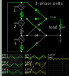
Simulation with a delta formation, sine-like current waveforms coming from each of the 3 supplies. Power factor is good because voltage and Ampere waveforms align.

3-phase delta totem 230vac 50Hz 6 diodes load 100ohm 310vdc.png

This does not have the 'funny bumps', whereas the star formation with neutral wire (image in post #22) does have them.
 

Even a simple resistive load after the bridge has neither a good PF nor a good crest factor.

View attachment 151808

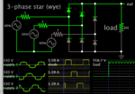
Returning to your plot with the 'funny bumps'. The scope trace has misaligned voltage and current waveforms. It would mean poor power factor. However my simulation has them centered in each AC supply, and it's a star arrangement (like your post #22 schematic).

3-phase star each 230v ac 6 diodes load 100 ohms.png

Scope traces at left have Voltage= green, Amperes= yellow.

Scope traces in middle show Amperes through upper diodes.

I suspect your scope traces combine voltage waveform from one source, with Ampere waveform of another source.
 

Status
Not open for further replies.

Similar threads

Part and Inventory Search

Welcome to EDABoard.com

Sponsor

Back
Top