Continue to Site

Welcome to EDAboard.com

Welcome to our site! EDAboard.com is an international Electronics Discussion Forum focused on EDA software, circuits, schematics, books, theory, papers, asic, pld, 8051, DSP, Network, RF, Analog Design, PCB, Service Manuals... and a whole lot more! To participate you need to register. Registration is free. Click here to register now.

I/O Digital port-current-voltages etc..

Status
Not open for further replies.

Winsu

Full Member level 3
Joined
Oct 25, 2017
Messages
174
Helped
2
Reputation
4
Reaction score
4
Trophy points
18
Activity points
1,691
Hi All,

I need to modify an existing circuit that uses the PIC32MX695F512H. I just need to use two digital I/O. I have identified the pins that I want to use:


Pin 54 will be a digital input which will be connected to another IC. That IC will pull down the signal to cero ( 0.3v) when an event happens. So I'm planning to use a pull-up resistor connected to Vdd( 3.3V). Using a 10k resistor I should be in safe side, but I would like to do the calculations ( knowing what I'm doing) and fully understand it as I'm not very familiar with microcontrollers. I can read some relevant information about currents In and Out from I/O pins and I don't know which one applies to my case. On page 360 I can see Icnpu ( change notification Pull-up current) which is 50uA.On page 361 I can see Input high injection current which is 5mA. on page 362 I can see Iol<10mA, Vdd = 3.3v( for all I/O pins not defined as 8x sink diver pins) and Iol<15mA. What current this pin would tolerate? and would it recognize 0.3V as Low and 3.3V as high?.

Pin 42 will be a digital output. It will be used to disable some LEDs which are permanently on, it will be done by connecting the digital output to the base of a transistor, then I can control the LEDS that are permanently on.
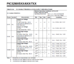
The relevant information that I have found is the next: On page 362 Output low voltage is 0.4V and output high voltage is 2.4V and Iol and Ioh cange from 10mA to 15mA. I wonder if this is the output range voltage that I can expect to choose the transistor and if that is current range that I can expect as well to attack the base of my transistor. I'm a bit confused also about the diference between source driver pins and not defined as source driver pins.


Any help would be very appreciatted.


Regards,
Winsu
 

Hi,

a simple - even hand drawn - schematic tells more than a lot of words. ...
please draw one.

Input current:
* "change notification inputs" are named "CNxx". Read section. 12.1.6 if you need this function.
If not needed --> dont care about it

* "input injection current" refers to current through the input protection diodes when the input voltag eis higher then VCC or lower than VSS.
--> you don´t need to care about his.

* "IOL" = I (current) for Outputs to drive LOW.
--> pin 54 is an input, thus don´t care about output specification.


Input pin:
you need to read "PIN INPUT SPECIFICATION" = Table 32-8.
* input low voltage = V_IL: worst case: 0.2 VDD. If VDD = 3.3V then this means 3.3V x 0.2 = 0.66V
--> with 0.3V you are safe.

* input high voltage = V_IH: worst case: 0.65 VDD. If VDD = 3.3V then this means 3.3V x 0.65 = 2.15V
--> with a high level of more than 2.15V you are safe

* input leakage current: idealy an input is considered as infinite high impedance. This means zero input current. But in reality there is a small current. in your case: +/- 1 uA.
To pull your input with 1uA to 2.15V with a pullup to 3.3V you need a resistor of maximum R = V / I = (3.3V -2.15V) / 1uA = about 1.1MOhms.
--> with 10k Ohms you are safe.


Output Pin:
You need to read "PIN OUTPUT SPECIFICATION" = Table 32-9.
--> Show your circuit.

Klaus
 

Hi,

Thanks for your answer.

Related with Input pin

As far as I understood my Pin 54 input should be fine if I put a 10K resistor. I said that the external IC would output 0.3V but it is because I measured it with a meter, it can actually be 0.5V as maximum. It is still within the LOW logic range, but what I could do to be more safe, should I put a 100ohm resistor in serie with the 0.5V line or it is too cautious ( or even wrong).

The leakage current means that I can't have more current In or Out than 1uA in that pin?, it defeats the table 32.9 when I can see more current going In and Out ( Output Pin). I know my last statement is wrong as I'm sure there is an explanation but I don't know why because as far as I know I can just set a pin as I/O no as only input or only output ( so I don't know why I can tolerate more current when it works as an output).

Related with output pin

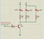
I have attached a schematic of the input pin and output pin. I haven't chosen yet a resistor and transistor for the Pin out as I don't how much voltage and current I will have available. The LED and resistor in serie with the LED cant be changed and I think they are irrelevant for this purpose as the LED bright fine with a 3.3V supply.


Thanks in advance,

Winsu Pins logic.PNG
 

Hi,

but what I could do to be more safe, should I put a 100ohm resistor in serie with the 0.5V line or it is too cautious ( or even wrong).
--> Do nothing. Else it will make it worse..

The leakage current means that I can't have more current In or Out than 1uA in that pin?
Not out. Leakage current is for inputs only.

Don't confuse yourself by looking into the wrong table.
Use the input table for inputs
Use the output table for outputs.

so I don't know why I can tolerate more current when it works as an output
An input needs no current ... at least modern CMOS ones. And one does not want current at inputs.
The less current the better. But there is unavoidable current. We have to live with this low currents. ...usualky they are low enough not to cause a problem.

The opposite is with outputs. ...Indeed not the output needs current but the load needs current ... from the output pin.
Examples: A LED, a transistor, an optocoupler ... or anything else you want to drive with your output.
And if you want to drive LOW you want the voltage to be close to 0V, even if there is some current...the same us with HIGH, here you want the output voltage close to VCC.
But on the silicon chip there are limits, thus one decided specifications for currents and voltages.
You can find them in the "output" table. Often there even are V - I - charts, where you can read the output voltage vs output current.

Your schematic:
Input circuit is correct.

"Both pins will be configured as bidirectional I/O".
Wrong.
Configure the input as input.
Configure the output as output.

Output circuit is wrong. Q1 needs to be an NPN with emitter to GND.
Without LED specifications one can only guess.
Maybe drive the transistor base with 1mA..
To calculate the resistor value you need the voltage:
It is: V_R = V_OH - V_BE .... I guess about 3.2V - 0.6V = 2.6V.
R = V / I = about 2600 Ohms. --> try 2.7kOhms

LED current limiting resistor: just guessing .... 47Ohms

Klaus
 

Hi,

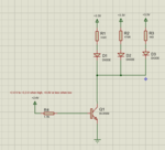
Thanks for the answer it has been very useful. I'm attaching the schematic for the digital output pin, it is actually controlling 3 different LEDs with different power supplies. I have calculated the Ic max which is 34mA between the 3 LEDs, so I'm planning to choose a NPN with a I max colector of 100mA and a hFE of 110 ( I just need 35 hFE but there is a wider range to choose with 110 gain). So the transistor that I'm picking is the BC847,215 of NXP. I'm supposing a 5mA output current for the digital output as its maximum output is 10mA, then the resistor is Rb = 330Ohm.

If the VOH was 3.3V instead of 2.4V( Pic datasheet just specifies minimum Output high voltage but the supplu for micro is 3.3V) the base at the current would be 8mA and if the Vbe sat decreases 0.2mV per degree, could I be in danger situation when the transistor was in a hot environment ( which I know it will)?. Should I choose a 1mA base current to be safer?.

Transistor for dig pin output.PNG

Cheers,
Daniel.

- - - Updated - - -

Coudl I choose 1mA base current with teh same transistor?.
 

Hi,

You know there are numerous tutorials according
* Ohm´s law
* LED resistor calculations
* basic transistor calculations.
Please go through them. they are for free. We can´t replace studying basics on your own.

********
Again there are several mistakes.

Ohm´s law applies for a resistor. With the voltage_cross_the_resistor and the current through the resistior.
Don´t use supply voltage or V_OH.

* 34mA is not correct, because you don´t care about the voltage drop at the LEDs.
* I doubt that LED1 and LED2 will ever be alight
* h_fe is for "linear" operation of the transistor. But here it is a ON/OFF "switching" situation.--> use a I_C/I_B of 10 as rule of thumb.
* 330 Ohms is wrong, because you don´t care about V_BE of the resistior. --> see my example in post#4

Klaus
 

Hi,

LED1 and LED2 are two LEDs that are already lighting in an existing board with those values. The have very low forward voltage. That's why I didn't include the Vf in the total current calculation ( but I agree with your comment, they look like they wouldn't light at all).

I have included the hfe in my comments because I have seen a tutorial to connect a transistor to a digital IC's on/off output, and they were recommending that the hFE has to be 5 times bigger than I load/max. IC current ( I was a bit confused about max.IC current as I don't know if it is max Ib or actual max IC output current). I attached the link of the tutorial.

https://electronicsclub.info/transistorcircuits.htm

I guess if I apply enough voltage between base-emitter the transistor will get in saturation for sure ( typically 0.6-0.7v). Then I would just need to calculate the resistor in the base to a fix current value ( lets say 1mA) and make sure the transistor supports enough Ic ( current collector ) needed for my load.

Cheers,
Winsu
 

Hi,

LED1 and LED2 are two LEDs that are already lighting in an existing board with those values. The have very low forward voltage. That's why I didn't include the Vf in the total current calculation
I've never seen LEDs with such low forward voltage. What type and manufacturer are they?

Klaus
 

Hi Klaus,

I was wrong about the LEDs, I was measuring voltage not along the whole track( resistor and LEDs ) and I assumed different voltage. The supply voltage is 3.3V for all the LEDs ( those LEDs would have been too good...hehehe).

I calculate max load current 40mA ( which in reality it will be less than 40mA as I'm not taking in consideration forward voltage of LEDs). If transistor works in saturation the worst case would be 24mW ( if we assume 40mA and max Vce sat 0.6V), which is far from max transistor dissipation( 250mW). I think the schematic that I'm attaching now should work now. I'm attaching as well the pin output specification for the PIC32M695F512H to make full sense.

Pin output specifications.PNG

Transistor for Dig output LEDs.PNG

I will have to readjust the original values for the load resistors as I will have now some voltage dropping between collector and emitter when in saturation, but I reckon it won't be a big change.

Regards,
Winsu
 

Status
Not open for further replies.

Similar threads

Part and Inventory Search

Welcome to EDABoard.com

Sponsor

Back
Top