Continue to Site

Welcome to EDAboard.com

Welcome to our site! EDAboard.com is an international Electronics Discussion Forum focused on EDA software, circuits, schematics, books, theory, papers, asic, pld, 8051, DSP, Network, RF, Analog Design, PCB, Service Manuals... and a whole lot more! To participate you need to register. Registration is free. Click here to register now.

Measuring a voltage that is higher than supply voltage

Status
Not open for further replies.

gn7623233

Newbie level 6
Joined
Oct 18, 2016
Messages
12
Helped
1
Reputation
2
Reaction score
0
Trophy points
1
Activity points
148
As Title
If supply voltage is 5v.
How can I measure voltage that is beyond the supply voltage using ADC?
Thanks everyone.
 

Hi,

Use two resistors as voltage divider.

Klaus
 

But use the resistors as voltage divider will reduce the SNR.
Is there a better solution?
Thanks.
 

Hi,

But use the resistors as voltage divider will reduce the SNR.
You care about SNR.
This means you want precision. (?)
Are you sure all your other components in the signal path (including ADC, if used) do not decrease SNR more than the resistive divider?
We can discuss about SNR, if you can give your overall SNR requirement.... and show the circuit of the complete signal path.

From my experience regarding SNR: The resistive divider is one of the least problemtic parts of a circuit.

****
Better solution:
My personal opinion: It´s uselss to discuss unless you have specification / reqirements.

We don´t even know:
* signal input voltage range (Is it 6V or is it 6000V)
* resistor values / expectable current / expectable power dissipation
* frequency range (is it DC only or audio, or RF?)
.. and these are the most basic values, only.

Klaus
 

Sorry. I should weight my words well. @@

Supply voltage is 5v, and measurement voltage range is a dc voltage about 5.1v.

I want to obtain step response amplitude between initial and steady state voltage.

Is there a another method? QQ

Thank u
 

You still missed to tell tell intended measurement voltage range.
 

Voltage range is a dc voltage about 5.1v to 5.15v.

Thank you.:cry:
 

What's the full range? 5.1 to 5.15 or 0 to 5.15?
 

Hi,

We have to guess: I assume the voltage range of interest is 0V ... 5.15V DC.

My recommendation: Add some headroom. So you are able to identify the range of interest as valid ... and you are able to identify "out of range" input.

***
Please understand:
I want to obtain step response amplitude between initial and steady state voltage.
This is about no information.
No calculator accepts inputs like "step response amplitude"... nor do I know how what you mean ... and how your circuit may look like. I have no idea about your requirements.

***
Is there a another method? QQ
A DVM, a scope?

Klaus
 

Try installing a series diode (or two, or zener, or led) as a means to subtract a couple volts from an incoming signal. The AC waveform comes through. You may find that a certain threshold current needs to flow, so you can take a usable reading.
 

There is no voltage drop on the two nodes of the diode when connecting it between the input signal and the ADC, so I guess the method of using the diode might not work.
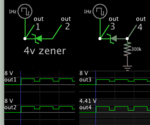
 

There is no voltage drop on the two nodes of the diode when connecting it between the input signal and the ADC, so I guess the method of using the diode might not work.

Some small amount of current needs to flow. Install a pulldown resistor, say between 50k and 500k ohm.

diode component needs small current flow via pulldown resistor.png

- - - Updated - - -

At left: No current flows. Notice voltage out is the same as voltage in.

At right: Current through the diode creates voltage drop while carrying noise on signal.

This works in simulation although the principle should be evident in hardware.
 
Hi,

A diode isn´t cheaper than a resistor.
And a resistor includes negligible temperature drift compared with a diode.
The diode drift will be about 2.1mV/°C and is not predictable ... unless you have an additional temperature measurment

The diode current varies with input voltage. And thus the diode voltage drop will add some new unlinear errors.
Input voltages from 0V ...0.5V leads to about zero output voltage is thus is not decodable.

In total for a 10 bit, 5V FS ADC input this means:
* 1/10 Resistor: input voltage range: 0V ..5.5V, which mans 5.37mV/LSB
* Diode: the input voltage range is 0.5V ... 5.5.V which means about 4.88mV/LSB ... this looks like an improvement.
But you pay this improvement of 0.5mV of resolution with about 21mV (or 4.3 LSB) (at +/-5V ambient temperature variation) added error.

On a resistor with tc = 100ppm/°C the expectable unpredictable error (precision) should be about 1LSB (5.4mV)

--> you loose precision. And as soon as the precision error is higher than 1LSB you loose overall performance.

****
Zeners with V_Z about 5V have low tc. Maybe here it is possible to gain performance. (needs calculation) ... but in the OP´s application a 5V zener makes no sense.


Klaus
 
Reply to BradtheRad :

Thank you for the simulation.
From the diode waveform simulation, I think the positive node of the diode should be connected to the input signal Vin, and the negative node of the diode is Vin-0.7. Out1 and Out3 are the negative of the diode, why the input signal is connected to the negative node?

The left figure shows that the two nodes of the diode have the same voltage. When the diode is floating and applying a voltage Vin at a positive node of the diode, the parasitic capacitor from the diode makes the negative node voltage is equal to Vin.

Diode with large resistor idea is good, but it has the drawback as KlausST mentioned.

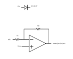
Or maybe the high input signal can be attenuated through an op-amp as bellowing figure, then scaled down signal can be processed by ADC.

1.PNG
 

Status
Not open for further replies.

Part and Inventory Search

Welcome to EDABoard.com

Sponsor

Back
Top