Continue to Site

Welcome to EDAboard.com

Welcome to our site! EDAboard.com is an international Electronics Discussion Forum focused on EDA software, circuits, schematics, books, theory, papers, asic, pld, 8051, DSP, Network, RF, Analog Design, PCB, Service Manuals... and a whole lot more! To participate you need to register. Registration is free. Click here to register now.

How to connect DL-CT1005A current transformer?

Status
Not open for further replies.

eagle1109

Full Member level 6
Joined
Nov 20, 2014
Messages
390
Helped
4
Reputation
10
Reaction score
7
Trophy points
1,298
Location
Saudi Arabia
Activity points
5,924
Hello,

I got this project from this website:
https://electronicsforu.com/electronics-projects/overload-protector-ac-motors

The page has everything, from schematic, block diagrams, PCB layout and final implementation picture.

I have most of the parts, I bought the current transformer DL-CT1005A but I don't know how to connect it. I've looked for any info about the connection of this current transformer but I could not find any circuit which have the actual pin connection and which pin goes to which line .. etc.


This is the best page which has a lot of info about it and the names/number of the pins, but there's not diagram of how to connect it.

According to the schematic diagram of the project webpage, the coil side is connected to the GND and the 2nd pin goes to the LM339 comparator. The other two pins on the other side are the ones which I don't know how would they work!?

I measure the connectin between them with the DMM but there's no connection, they seem to be open. But they are connected in series with the motor. But how they work?
 

You misunderstand the diagram. The motor circuit is connected to a wire through the central CT opening, not the other bottom pins.

The other pins are only for mounting purposes and have no electrical function. According to product description, it's a standard AC current sensor with 2000:1 winding ratio. Maximal burden resistor is specified with 250 ohm for 0.1% linearity.

The circuit in the link is a bad design, it may be damaged by motor inrush currents and respective high voltage at the almost unterminated CT. You better refer to known working CT circuits from other web sites.
 
eagle1109:
The wire to the motor goes through the center of the current transformer.
The bottom center of the PWB has two connections for the current transformer, CT1, which is NOT mounted on the PWB.
Two of the pins on the bottom of the current transformer are for connecting to the circuit. One goes to the rectifier and
the other goes to ground. Since it is AC, it probably doesn't matter which pin goes where.
The other two pins are not used electrically and are mechanical mounts.
 
You misunderstand the diagram. The motor circuit is connected to a wire through the central CT opening, not the other bottom pins.
omg I just noticed that !! thank you so much for the declaration.

The other pins are only for mounting purposes and have no electrical function. According to product description, it's a standard AC current sensor with 2000:1 winding ratio. Maximal burden resistor is specified with 250 ohm for 0.1% linearity.
Yes, how to get advantage of this information? For now, what I learned is that the designer of the project chose this current sensor, so it should work fine, should I care about one or more of these parameters?

The circuit in the link is a bad design, it may be damaged by motor inrush currents and respective high voltage at the almost unterminated CT. You better refer to known working CT circuits from other web sites.
But there's a relay, that's what I know is an isolation between the control circuit and the load circuit. Could you specify how could the damage happen with the use of a relay? Also we have relay breakouts that have protection parts; like, optocoupler .. etc.

Also, could you tell me about other better designs? Because it would take me a lot of time to search for a another design or think to design another similar system.


eagle1109:
The wire to the motor goes through the center of the current transformer.
The bottom center of the PWB has two connections for the current transformer, CT1, which is NOT mounted on the PWB.
Two of the pins on the bottom of the current transformer are for connecting to the circuit. One goes to the rectifier and
the other goes to ground. Since it is AC, it probably doesn't matter which pin goes where.
The other two pins are not used electrically and are mechanical mounts.
Thanks for the explanation.

But I haven't started to put the parts together and start testing the project, do you have any suggestion or your opinion about this circuit?

The main goal of this project is not to use a microcontroller for the control, so we want to run it with similar logic/linear ICs.
 

Hi,

But there's a relay, that's what I know is an isolation between the control circuit and the load circuit. Could you specify how could the damage happen with the use of a relay? Also we have relay breakouts that have protection parts; like, optocoupler .. etc.

The problem is not "isolation" or "relay".
The problem is the "open" output of the CT.

Open means high ohmic.
Now let's just do an example.
Let's say load current is 1A.
Because of the CT winding ratio of 2000:1 the CT tries to force this current at the output: I_out = I_in / 2000 = 1A / 2000 = 0.5mA.
A proper circuit has a fixed burden resistor at the output. Let's say 250 Ohms.
Then the output voltage becomes: V_out = I_out x Rb = 0.5mA x 250 Ohms = 125mV.

But your circuit has no proper burden resistor. The output is high ohmic.
Let's just imagine there is a steay impedance of 100k Ohms (caused by bad isolation and stray capacitance)
The the (theoretical) output voltage is: V_out = I_out x Zb = 0.5mA x 100.000 Ohms = 50V.

This is high voltage that may kill the "low voltage side circuit"
--> The higher the load current, the higher the output voltage
--> The higher the output impedance the higher the output voltage.
But the output voltage will not become infinite. It is limited by the unavoidable output impedance (it is limited, too) and the output voltage becomes limited when the CT core becomes saturated.

--> Thus a proper design never uses "open CT output".
It may use directly connected resistors, but one may add diodes (like your circuit). But even with diodes I recommend to use a symmetric output circuit: add a second diode and maybe a second burden for the opposite current direction to avoid core saturation causedby onsymmetries.

Klaus
 
Hi,

Now let's just do an example.
Let's say load current is 1A.
Because of the CT winding ratio of 2000:1 the CT tries to force this current at the output: I_out = I_in / 2000 = 1A / 2000 = 0.5mA.
A proper circuit has a fixed burden resistor at the output. Let's say 250 Ohms.
Then the output voltage becomes: V_out = I_out x Rb = 0.5mA x 250 Ohms = 125mV.

Klaus

and if the current is 10A, the output voltage is 1.25 V.
If you hang a differential amplifier, or an opamp follower on that, then rectify and filter it, you can connect if to the same two points in the schematic or PWB.

The documentation on the current transformer (that I found) wasn't clear which pins were the output pins.
You can find them by putting one side of an AC power cord through the center of the current transformer. Insert an AC current meter in the AC line. Then put a 100 ohm resistor across two of the pins of the current transformer. Turn on the AC device and observe the output across the resistor. The meter and the voltae across the resistor should be related with KlausST's equation above.
I believe the OP has already found the right pins by using a DMM...
 
Hi,
The problem is not "isolation" or "relay".
The problem is the "open" output of the CT.

Open means high ohmic.
Now let's just do an example.
Let's say load current is 1A.
Because of the CT winding ratio of 2000:1 the CT tries to force this current at the output: I_out = I_in / 2000 = 1A / 2000 = 0.5mA.
A proper circuit has a fixed burden resistor at the output. Let's say 250 Ohms.
Then the output voltage becomes: V_out = I_out x Rb = 0.5mA x 250 Ohms = 125mV.

But your circuit has no proper burden resistor. The output is high ohmic.
Let's just imagine there is a steay impedance of 100k Ohms (caused by bad isolation and stray capacitance)
The the (theoretical) output voltage is: V_out = I_out x Zb = 0.5mA x 100.000 Ohms = 50V.

This is high voltage that may kill the "low voltage side circuit"
--> The higher the load current, the higher the output voltage
--> The higher the output impedance the higher the output voltage.
But the output voltage will not become infinite. It is limited by the unavoidable output impedance (it is limited, too) and the output voltage becomes limited when the CT core becomes saturated.

--> Thus a proper design never uses "open CT output".
It may use directly connected resistors, but one may add diodes (like your circuit). But even with diodes I recommend to use a symmetric output circuit: add a second diode and maybe a second burden for the opposite current direction to avoid core saturation causedby onsymmetries.

Klaus

Yesterday the student brought a hair dryer motor which work on 220V/AC with a fan as a load and this current sensor module:
arduino-iot-0-5a-ac-current-sensor-transducer-module-iFuture-baroda-vadodara-gujarat-india-asia.jpg


It doesn't have aux protection components, so it's similar to the one in the project circuit.

We did an experiment:
1. We connected a DMM in series with the motor with the fan attached and the current was 0.7A and was dropping until it reached like 0.599A. I don't know why it was dropping, maybe the motor got warm so it draws less current but the performance also got degraded too, so maybe the motor isn't an optimum one.
2. Without the fan the current is 0.2A.
3. The AC output voltage from the sensor is 125mV/AC with the load connected, but we didn't measure it without load but it should be something like ~70mV or less.


So now this the voltage coming out of the sensor, but I didn't measure something really high as you warned me about, so now should I worry about the setup?

This is just experimenting the 1st stage which is to measure the motor current and the current sensor output as they are the most important parts of the project.
2nd stage is to connect the current sensor output to the LM393 comparator and as adjust the output of the comparator that if the voltage is 125mV which is the one at the load attached then the relay is activated and shut-off the motor, it's just for demonstration, and if the voltage is less than 125mV; say something like 70mV, then operation is safe and relay isn't activated.


How about this analysis?
 

Hi,

It doesn't have aux protection components, so it's similar to the one in the project circuit.
We didn´t talk about a protection circuit. We talked about proper installing a burden resistor ... and not leave the CT output high ohmic (in one direction).

As already explained: High ohmic causes high voltage.

but it should be something like ~70mV or less.
Why not zero?
No input current --> no output current

but I didn't measure something really high as you warned me about
No wonder.
It clearly has the burden resitor installed: next to the connector, marked with "102", wich means 1kOhms.

is to connect the current sensor output to the LM393 comparator and as adjust the output of the comparator that if the voltage is 125mV which is the one at the load attached then the relay is activated and shut-off the motor, it's just for demonstration, and if the voltage is less than 125mV; say something like 70mV, then operation is safe and relay isn't activated.

Why don´t you use a sheet of paper, draw your circuit and draw the waveforms. This is not only useful for professionals. .. (I really do it all the time)

How does a 125mA AC signal look like? Draw a diagram.
Then draw the comparator threshold level into your diagram. A single straight horizontal line.
When the AC signal is higher than the threshold signal (= at the points where both signals cross) --> the comparator output will be HIGH. Draw this in your diagram.

Is this what you want?

Don`t get me wrong. For sure it would be easy to design the circuit for you ... but then you will gain nothing ... and next time you still are not able to analyze the circuit/problem on your own. I hope you are interested in learning for the future. We will help you with this.

Klaus
 
Hi,

Sorry for late response, I just worked a little on the setup yesterday, connected the oscilloscope in different circuits, as follows:

1. Motor, current sensor (including burden resistor) with diode + load resistor. But the result isn't as expected! Actually my experience with signals is very low, I have one time measured the signals coming out of the rectification diodes on the output side of SMPS. But this one is really different.
diode&resistor.png


2. This one without the diode, only load resistor:
resistor.png


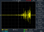
3. This is without anything, just connecting the GND & signal of current sensor directly to the oscilloscope rails:
Here I tried to capture the moments where the signal has the most stress, there are other pictures with low amplitude.
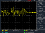
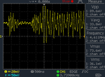
First part with the fan connected to the motor as a load:
fan.png


Second part without the fan:
nofan.png


=======================================================================================

This is my initial testing, planning to go more the next time.
 
Last edited:

Hi,

Why the diode and the "load resistor".
What´s the idea behind this circuit?

Klaus
 
If you look closely at the photo:
Between the output connector and the transformer's body, there appears to be a 200 ohm resistor (barely seen as 201).

In other words, it is already terminated into a burden resistor.

- - - Updated - - -

Hi,

3. This is without anything, just connecting the GND & signal of current sensor directly to the oscilloscope rails:
Here I tried to capture the moments where the signal has the most stress, there are other pictures with low amplitude.
First part with the fan connected to the motor as a load:
View attachment 151898


Second part without the fan:
View attachment 151899


.

An oscilloscope timebase of 500nS/ division..oooooooohhhhhh nooooooooooooooooooooooooooo!!!!

Try 20,000 times slower: 10 mS/division
 
Hi,

Why the diode and the "load resistor".
What´s the idea behind this circuit?

Klaus

Because the circuit schematic has a diode for filtering out the -ve part of the CT output signal. The resistor is just that I was afraid that I may short something so I put that resistor.

It was like I'm connecting a complete circuit. Because when I connected the diode, I didn't know for sure where to connect the cathode, which should be at least connected to the ground which is the ground of the oscilloscope.

I have no much experience of why there is a capacitor and resistor to the ground at point NO.2 on the picture!

ckt_mod.jpg

If you look closely at the photo:
Between the output connector and the transformer's body, there appears to be a 200 ohm resistor (barely seen as 201).

In other words, it is already terminated into a burden resistor.
Yes, I know that there's already a burden resistor, which Mr Klaus told me in earlier posts, but I put another one in series with the output of the CT as a load or at least protection, I know the signal is 125mV it's really very small, but when putting that resistor the output changed.

As I have no much experience of how a circuit should behave especially when it comes to AC signals, but I started to learn something, for example, first I expected the CT output signal to be pure AC signal like the mains AC signal, but there was like distortion, so I learned that's the stress of the motor windings.


- - - Updated - - -


An oscilloscope timebase of 500nS/ division..oooooooohhhhhh nooooooooooooooooooooooooooo!!!!

Try 20,000 times slower: 10 mS/division

OK, it just this one was clear to study the behavior of the CT output signal.
 

I need a help with the op amp.

I know it's an easy thing, but I actually have very little knowledge of how this thing work?!

I need it because I want to amplify the signal coming from the CT. Is that a good idea?

That was my quick solution for the small signal coming from the CT as it's really small in mV range. So my solution was to include an op amp.

I have the 741ua. I want to connect it as a voltage amplifier, to amplify the signal.

The CT signal has a +ve and -ve peaks, so I know I have to include a -ve voltage source in the implementation.

Now I'm just connecting the op amp with a 5V voltage source and I just want to test how this thing amplify a signal, but I guess I have little experience of how to do that.

I'm putting 1k resistors on the inverting pin to GND and also 1k from output to pin 2.

And connecting a variable resistor on pin 3 to identify the amplifying action, but it's not working as I would expect.

I know there's something I have to adjust at the feedback resistor. It's almost the same, except I'm connecting a pot at the input.

I'm applying this basic circuit:
**broken link removed**
 

It would be a good idea to complete the schematic with power supply and signal source. Otherwise there are many possible misunderstandings and many ways to make the circuit fail, e.g. due to incorrect DC bias.

If we read the said "5V source" as 5V single supply, then the circuit can't work.
 
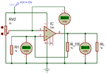
I've tried this circuit on Proteus.

op_amp_test.png

RV2 - input variable resistor
R1 - inverting pin protection resistor, it's my guess I'm not sure what's the purpose of this resistor.
R2 - feedback resistor which determine the closed loop gain
R3 - normal load resistor, not necessary I guess.


Theoretically, it should work as voltage gain of 2x. But, I've done the same circuit on the breadboard, and I get different results.

when I change the variable resistor of the input voltage, I get 3.7V and 4.3V only .. two states of voltages. No linear amplification of voltage as I expected.
 

R1 and R2 determine the gain
as you said, the gain should be 2 because this op amp is wired as a non-inverting amplifier, so Vout (at pin 6) = V+ (at pin 3) * (1 + (R2 / R1) )
since R1 = R2, gain is 2.

I don't know how good the model of the op amp in Proteus is, but I think you may be overloading the output.
4V across 100 ohm is is 40 mA, which may be beyond the capability of a 741 op amp
try making R1 and R2 both between 4700 ohm and 10 kohm and R3 1000 ohm.
if Proteus models the current capability of the op amp, this might look more like what you expect.

the three voltmeters show 88.8 V. how did you get 88V? if i recall correctly, a 741 is 30V max from pin 4 to pin 7

is RV2 fixed? at what value?
real op amps need 1 to 2 V overhead - that is, the maximum (minimum) input voltage must be 1 to 2 V less (more) than the +rail (-rail)
(rails being the voltages of the power applied at pins 7 and 4)
741 has been around a long time and falls into this class.

what do you get on your breadboard?
 
Sorry for the unclear simulation snap.

Here's another photo with the few changes:

op_amp_sim1.png

In simulation, it works perfectly, in real world which is of course the most important for consideration.

But I went back to simulation, because things didn't work as expected on breadboard. I spent all my time yesterday trying to get this circuit to work.

But what's the actual theory and principle of operation to the op amp?

First of all I got the UA741CN, I don't know if it has different operation than the LM741.

I just downloaded the datasheet and it seem to be a nothing different than the ordinary op amp operation that I know.

Here's the application circuit in the datasheet:

ua741cn_noninv.png

The additions I noticed are two bypass capacitors, which are not necessary for the simple test implementation.
 

Hi,

The additions I noticed are two bypass capacitors, which are not necessary for the simple test implementation.
In simulation you don'tneed them.
At a PCM I add them
But for a breadboard they are more important then elsewhere, because with a breadboard you have the highest impedance at the supply pins, caused by lengthy wiring.

****
To your functional problem:
Your error description is not clear to me. I don't know where exactly your expectation differes with what you get.

Klaus
 
741 (any variant) isn't suited for single supply operation. Minimal supply voltage according to datasheet is +/- 5V, usable input voltage range starts about 2 above negative supply. A low voltage, single supply OP like LM358 may be better suited for your purposes.

You state correctly:
The CT signal has a +ve and -ve peaks, so I know I have to include a -ve voltage source in the implementation.

I don't see this idea considered in any of your OP schematics.
 
Status
Not open for further replies.

Part and Inventory Search

Welcome to EDABoard.com

Sponsor

Back
Top