Continue to Site

Welcome to EDAboard.com

Welcome to our site! EDAboard.com is an international Electronics Discussion Forum focused on EDA software, circuits, schematics, books, theory, papers, asic, pld, 8051, DSP, Network, RF, Analog Design, PCB, Service Manuals... and a whole lot more! To participate you need to register. Registration is free. Click here to register now.

Opamp current regulator trying to limit overshoot in LED current

Status
Not open for further replies.
T

treez

Guest
Hello,
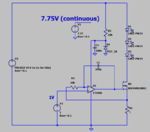
The two current regulators here try to keep the LED current from overshooting too much each time the LED voltage supply turns back ON.
The one with the zener diode has the advantage that its opamp’s output voltage never gets railed high, and so it should offer less overshoot in the LED current when the LED supply voltage comes back on, however, its overshoot is just as bad as the other one, whose output does rail high.
Why is this?
Ie, Why does the opamp whose output gets railed high not incur greater led current overshoot than the other one?
I mean, when the opamp output rails high, the opamp’s output stage goes into saturation, and so it should take more time to bring its output down from the high rail? (and thus incur greater overshoot in the led current when the LED supply voltage comes back on)

LTSpice sim and pdf schem attached
 

Attachments

  • Current regulators with pulsed LED voltage.pdf
    18.5 KB · Views: 90
  • Current regulators.txt
    4.3 KB · Views: 69

Your pulse supply is 24V. The voltage drop on the LEDs is typically 3 to 3.5 V. Therefore, there will be 12 to 10.5V across R3, the only thing that could limit current at turn on, as the op amp and FET will be ON.

When the pulse is off, there is no current in the LEDs and R1. The op amp and the FET are driven ON.
When the pulse turns on, there is about 11V difference between the pulse supply and the LED's drop. That 11 V shows up across R1. The opamp and FET looks like a switch, because the 11 V on R3 overdrives the inputs.

Now that the opamp sees 11V at the - input, it turns off, again, overdriven

I suggest you determine what current you want through the LEDs for the luminosity you want.
Then insert a resistor where R = 11V / desired current between the pulse source V2 and the first LED D1.

I also think you should reduce the voltage of the pulse source, a the resistor I suggest you use will dissipate about 11 W at 1 A.

An alternative is to use a linear current limit circuit.
Lose the op amp, C1, R2, V3. Put a resistor, about 10k on the drain to gate of the FET.
add a small transistor, like a 2N2222A, collector to gate, base to drain and emitter to ground.

Change R1 to R1 = 0.6V/desired current limit. R1 controls the behavior of the 2N2222A. When the desired current passes through R1, the transistor starts turning on, controlling the current by controlling the gate of the FET.

When there is no current, the 2N2222A will be OFF, and the FET will ???.
When the pulse turns on, the current will rise in R1, turning the 2N2222A and the FET ON. The current in R1 will cause the transistor to pull the gate of the FET down, forcing the FET to move toward OFF, reducing the current and lowering Vbe, etc.
It regulates and cannot behave like a switch.

I assumed you chose the FET for the appropriate voltages, current , power and SOA.
 

sorry, the above in post #1 says "7.2V" but it is supposed to be "7.75v"......(the sim was 7.75v anyway fortunately).
Attached are the corrected ones

- - - Updated - - -

Thanks, your observations are of course correct, .....really, i am asking, when an opamp output goes to its rail, then does it "stick" there a little?...ie, take a bit of time to come off the rail because of the output stage of the opamp getting saturated?....then the minority carriers have to be dispersed before the opamp output can come off the rail?....kind of like when a NPN BJT goes into saturation..........ie VBE and VBC going forward biased and then to get out of it the minority carriers need to be flushed out, and this takes time.
Is this what kind of happens with an opamp output when it gets railed as in the above example?
 

Attachments

  • Current regulators with pulsed LED voltage.pdf
    18.2 KB · Views: 70
  • Current regulators.txt
    4.3 KB · Views: 59

You get a kind of controller windup when the 24 supply is off. The zener diode limiter is apparently not specific enough to avoid it. You can either try to drive the controller supply from 24V input or add a shutdown and soft start feature that is controlled by the 24 V input.

Which real world setup is modelled here? 1 us rise time for the pulsed power supply looks a bit unrealistic.

- - - Updated - - -

The observed behavior has nothing to do with OP saturation or so. It's caused by the RC time constant you have designed into the circuit and the limited OP bandwidth and slew rate in addition. The simulation can you show clearly how it's brought up.

- - - Updated - - -

This works quite well

alt.PNG
 
  • Like
Reactions: treez

    T

    Points: 2
    Helpful Answer Positive Rating
Consider the TL431 topology at this link. It could do three things for you:
1) It's a bit simpler because:
2) It includes the reference
3) If run from 24V it shouldn't have startup overshoot

https://hopkinsdev.blogspot.com/2016/09/constant-current-led-driver-with.html

Choose a 1.24V TL431 variant and you'll have close to the 1V chosen now.


Depending on how much accuracy matters and if you're really running 3 LED's off 24V and dropping over 10V I'd also consider this topology (its accuracy improves with voltage since the Vgs/Vbe threshold variation starts to matter less).

https://en.wikipedia.org/wiki/Current_source#/media/File:Const_cur_src_111.svg
 
  • Like
Reactions: treez

    T

    Points: 2
    Helpful Answer Positive Rating
This shows the basic zener+transistor approach which works well.

It also shows your basic circuit but details the 1V reference as a shunt reference that's pulled up to the 24V ensuring it goes away when 24V does. The final 'trick' is to slightly bias the negative feedback to ensure offsets are overpowered and force it to saturate negative.

I'd like to simulate the TL431 variant but my new install of LT doesn't have a good model for one....(I'm not missing a built in TL431-like model am I?)


Capture.PNG
 
  • Like
Reactions: treez

    T

    Points: 2
    Helpful Answer Positive Rating
Thanks, im not sure how good this TL431 model is (attached), but please try it if you wish
Its from Helmut Sennewald many years ago, who used to run the ltspice forum on yahoo groups
 

Attachments

  • LTspice _TL431 MODEL FROM HELMUT.zip
    1.2 KB · Views: 66
  • Like
Reactions: asdf44

    asdf44

    Points: 2
    Helpful Answer Positive Rating
Why don't you try yourself, it's your project? TL431 or an 1.2 V type like ZRE124 works perfectly for it, minimal part count.
 

Hi,

I'd like to simulate the TL431 variant but my new install of LT doesn't have a good model for one....(I'm not missing a built in TL431-like model am I?)View attachment 151477

Along with treez's suggestion, if TI Tina Spice models (Spice Model, PSpice Model) can be used in LTSpice, the TI TL431 page has the two aforementioned models there. In my limited knowledge of simulators/models, it seems to me that the version in TINA is more than adequate for realistic simulation purposes; I've used it in a lot of simulations as either a standalone adjustable reference or as part of a voltage regulator circuit block.

TL431 Models (5)
 

Why don't you try yourself, it's your project?
my apologies, i thought asdf44 was suggesting a desire to have a good TL431 for asdf44's own personal use, so i offered one up.
 

Well yes, I was somewhat lamenting that it appears neither Linear nor Analog (as Analog parts are now quickly being added to LT) have a basic TL431 variant.

In my old install of LTSpice I had added many TL431 models but none of them performed well consistently, and my new install I haven't bothered adding anything yet.

At some point I'll try yours Treez although I almost always use the 1.24V variants, though in simulation many times it doesn't matter too much.
 
  • Like
Reactions: treez

    T

    Points: 2
    Helpful Answer Positive Rating
Status
Not open for further replies.

Part and Inventory Search

Welcome to EDABoard.com

Sponsor

Back
Top