Antor
Member level 2
Hello there,
I have a spice file for a component and I need to create this component in ISIS and make it able to simulate.
Datasheet link
Here is the spice model for the component.
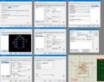
Here is the path I followed to create the component and fail

What am I doing wrong ? Or what I should do ?
Thanks for help.
I have a spice file for a component and I need to create this component in ISIS and make it able to simulate.
Datasheet link
Here is the spice model for the component.
Code:
* HCPL-3140/HCPL-0314 SPICE Macromodel
* Rev. B
* 07/07
* ZFC
*
* This is the behavioural model for the above-mentioned part number.
* It is valid for functional simulation over the range specified below.
* Supply range: 10 to 30V
*
* Macromodels provided by Avago Technologies are not warranted
* as fully representing all of the specifications and operating
* characteristics of the product.
*
* Macromodels are useful for evaluating product performance but they
* cannot model exact device performance under all conditions, nor are
* they intended to replace breadboarding for final verification.
*
* Copyright 2007 Avago Technologies Limited. All Rights Reserved
********************************************************************************
*                 Anode(pin2)
*                  |    Cathode(pin3)
*                  |    |    Common(pin5)
*                  |    |    |    Output(pin6)
*                  |    |    |    |    Vcc(pin8)
*                  |    |    |    |    |
.SUBCKT HCPL3140  102  103  105  106  108
land 20  102 20n
lcth 23  103 20n
lgnd 10  105 20n
lout 3   106 20n
lvcc 2   108 20n
xled 20 23 22 23 led
rled 22 23 1meg
*This is Ith, bandwidth and amplitude limitation
gpd  10 1 22 23 1
ith 1  10  dc 4.3m
cb  1  10 0.16n
rb  1  10 1500 tc1=0.004
vlimitp  13 10 dc 1
vlimitn  14 10 dc -1
dlimitp  11 13 dmod3 1.430
dlimitn  14 11 dmod3 1.430
rlimit 12 11 1000
elimit 12 10 1 10 1
mshut 11 16 10 10 nmosmod l=10u  w=1000000u
.MODEL nmosmod nmos (vto=+0.7)
vshut 15 10 dc 5
rshut1 15 16 1000
rshut2 16 17 1000
eshut 17 10  2 10 -1
*This is output stage and gate drive
vinside 28 10 dc 30
ql1  3  6  10 npnmodL
ql2  28  7  6  npnmodL
dl1  10  3  dmod3 1.430
dl2  10  6  dmod3 1.430
dl3  6   7  dmod3 1.430
qh1  2  4  3 npnmodH
qh2  2  5  4 npnmodH
dh1  3  2 dmod3 1.430
dh2  3  4 dmod3 1.430
dh3  4  5 dmod3 1.430
gidh   3   5  11 10  0.0005
gidl  10   7  10 11  0.0005
*This is iccl 1.2mA current source cricuit
q3 51 50 2 pnpmod
q4 50 50 2 pnpmod
q2 50 52 53 npnmod
q1 52 53 58 npnmod
rst2 51 52 1000
riccl 53 58 1240 tc1=-0.003
qcl 58 59 60 npnmod
gcl 60 59 10 11 0.0001
qdl 60 61 10 npnmod
gdl 10 61 2 10 0.000003
d50 60 59 dmod3 1.430
d51 10 61 dmod3 1.430
rl 58 10 1000000
.MODEL pnpmod  pnp (bf=100)
.MODEL npnmod  npn (bf=100)
*This is icch 0.7mA current source cricuit
q13 151 150 2 pnpmod
q14 150 150 2 pnpmod
q12 150 152 153 npnmod
q11 152 153 158 npnmod
rst12 151 152 1000
ricch 153 158 2000 tc1=-0.0032
qch 158 159 160 npnmod
gch 160 159 11 10 0.0001
qdh 160 161 10 npnmod
gdh 10 161 2 10 0.000002
d150 160 159 dmod3 1.430
d151 10 161 dmod3 1.430
rh 158 10 1000000
.MODEL DMOD3 D IS=2.22P CJO=1P VJ=.376 M=.139 N=1.07
.MODEL NPNMODH
+ NPN
+ IS=1.27E-17 BF=550.35 NF=1.00 ISE=4.61E-17 NE=1.320
+ IKF=7.06E-3 BR=0.11
+ NR=1.00 IKR=10.4E-3 VAR=17.47 VAF=18 RE=4.26 RC=4.12 RB=6.85
+ RBM=68.65
+ CJC=84E-15 CJE=38E-15 CJS=520E-15 MJE=0.50 VJE=0.69 MJC=0.40 VJC=0.60
+ MJS=0.344 VJS=0.60 TF=305P XTF=0.43   ITF=12M
+ IRB=95U PTF=17  XTB=0.202 XTI=3.058 TR=85E-9 EG=1.167
.MODEL NPNMODL
+ NPN
 + IS=1.27E-17 BF=600.35 NF=1.00 ISE=4.61E-17 NE=1.320
+ IKF=7.06E-3 BR=0.11
+ NR=1.00 IKR=10.4E-3 VAR=17.47 VAF=32 RE=.136 RC=2.5 RB=6.85
+ RBM=68.65
+ CJC=84E-15 CJE=38E-15 CJS=520E-15 MJE=0.50 VJE=0.69 MJC=0.40 VJC=0.60
+ MJS=0.344 VJS=0.60 TF=305P XTF=0.43   ITF=12M
+ IRB=95U PTF=17  XTB=0.202 XTI=3.058 TR=85E-9 EG=1.167
.ENDS HCPL3140
.SUBCKT LED  1 2 7 4
RSERIES 1 5 2
DELECT 5 2 LEDNOR
ELED 6 4 5 2 1
DOPTIC 6 8 LEDNORC
VSENSE 8 4 DC 0
FPHOTO 4 3 VSENSE 1
RL 3 4 1 tc1=-0.00015
EOUT 7 4 3 4 1
.MODEL LEDNOR D IS=5E-16 N=2 XTI=3 EG=2.1 BV=5 IBV=10u
+  CJO=60p VJ=.75 M=.3333 FC=.5 TT=20n
.MODEL LEDNORC D IS=5E-16 N=2 XTI=3 EG=2.1 BV=5 IBV=10u
+  VJ=.75 M=.3333 FC=.5
.ENDS LED
Here is the path I followed to create the component and fail

What am I doing wrong ? Or what I should do ?
Thanks for help.