Continue to Site

Welcome to EDAboard.com

Welcome to our site! EDAboard.com is an international Electronics Discussion Forum focused on EDA software, circuits, schematics, books, theory, papers, asic, pld, 8051, DSP, Network, RF, Analog Design, PCB, Service Manuals... and a whole lot more! To participate you need to register. Registration is free. Click here to register now.

No phase delay, no amplitude loss, unity gain voltage follower help required

Status
Not open for further replies.

seyyah

Advanced Member level 2
Joined
Oct 7, 2001
Messages
646
Helped
8
Reputation
16
Reaction score
8
Trophy points
1,298
Activity points
6,233
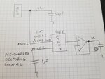
I have a intermixed input signal of 100 KHz (Ican reduce it to 50KHz if required) pulsed signal @5V and a very low frequency signal. In mode one, the input signal is high frequency; in mode two, it is near DC below 5V. I need an exact copy of this signal. I tried to use TL3472 in unity gain voltage follower but the output has amplitude loss.
What do you suggest me? I have OPA1662 and LM358 in my stock currently. I can buy another one if required.
 

Incomplete signal specification. What is "100 KHz pulsed signal @5V"? Rise time and pulse width matters, also source and load impedance.

It would be also helpful if you show what kind of signal distortion ("amplitude loss") you observed.

1 and 4 MHz GBW OPs are probably too slow, 22 MHz OPA1662 is better, 17 V/us slew rate may be still insufficient.
 

Hi,

"no phase delay" is not possible.
Better give a more useful specification.

in mode two, it is near DC below 5V. I need an exact copy of this signal. I tried to use TL3472 in unity gain voltage follower but the output has amplitude loss.
amplitude loss with DC input?
--> what is your circuit? What are your test conditions? What is your measuremnt equippment? What are the exact test results?

Klaus
 

The idea is something like the one in the attachment
 

Attachments

  • circuit.jpeg
    circuit.jpeg
    172.4 KB · Views: 130

The output RC shown has a cutoff of about 600khz. That's going to have more impact on gain and phase than the referenced Opamps.
 

If you stick with "no, no, 1.0000..." as requirements then
the problem becomes very easy - you can just quit now.

The highest closed loop BW is likely to be found in CFAs
but these don't always have the best input offset, and
they want current. Not a problem in 50-ohm systems
where they are often used, but not good for a high-Z
or variable-Z (such as a CMOS mux across temp & supply)
signal source.
 

Status
Not open for further replies.

Part and Inventory Search

Welcome to EDABoard.com

Sponsor

Back
Top