Continue to Site

Welcome to EDAboard.com

Welcome to our site! EDAboard.com is an international Electronics Discussion Forum focused on EDA software, circuits, schematics, books, theory, papers, asic, pld, 8051, DSP, Network, RF, Analog Design, PCB, Service Manuals... and a whole lot more! To participate you need to register. Registration is free. Click here to register now.

1.2KW Full Bridge Converter

Status
Not open for further replies.

ivan_mateo

Member level 1
Joined
Feb 11, 2019
Messages
40
Helped
1
Reputation
2
Reaction score
2
Trophy points
8
Activity points
385
Hi everyone,

I am planning to design a full bridge converter and it should be close to %92-93 efficiency. First of all, I need to overcome my transformer design problem.

In my calculation, the output voltage and current is 30V,40A and the output power is 1200W. The input power is around 1300W based on that efficency. The minimum input 170VAC, peak is 239,7V, Vavg is 152,6V.

I have chosen that ETD/44/22/15(Ve=17800mm^3,Ae=173mm^2) and N97 core which has 100mT at 100kHz,25'C. And 135.28kW/m^3 at 100mT. Pcore losses=2.4W. When I calculated my Nprimary turn using that formula V=4xNx2BxAexfs, Nprimary is equal 22T.

But in there my confusion is how to calculate my input current and from that Lprimary inductance. I have some knowledge about it that the inductane is proportional to the square of primary turns. And there is AL factor. L= ALxN^2

But also AL =1/Reluctance of core. And As I shown below document from TDK, there is AL value for N97 core and there is some info related to calculate Reluctance Me and le . But Al equal 1/Reluctance but when I calcuate it, it is not equal to AL calue for N97.

Can anybody help solve this step? Ekran Alıntısı.PNG
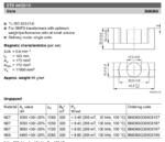
 

he minimum input 170VAC, peak is 239,7V, Vavg is 152,6V.
No PFC for 1.2 kW?

AL=1720*(4*Pi*10^-7)/(0.6*10^3)=3602,36 nH , close to datasheet value.
Reluctance=1/[1720*(4*Pi*10^-7)] *(0.6*10^3)=277595,831 H^-1
 
how to calculate my input current and from that Lprimary inductance.

Now that we have computers, simulators are a major labor-saving device.
This screenshot demonstrates output with a variety of primary Henry values.

Supply is 240V square waves. Load gets 30V 40A.
Transformers step down 8:1
I chose frequency 100 kHz just because it is mentioned in your specs.

4 transformer diff pri values 100kHz 240v sq wav load 1200W 30V .png

Notice that primary inductance does not need to fit in a narrow range. The third circuit (5mH pri) appears to draw reasonable Amperes from the supply, and delivers a proper waveform to the load at 30V 40A. It is not so bad even with the second circuit (0.5mH). So theoretically it looks as though it would work okay with a primary value between .5mH and 10 mH.

If primary inductance is high, then you need to reduce frequency if you wish to get efficient performance from your transformer.
 
It's nor clear what are you designing at all. A transformer, an inductor? In case of a transformer, primary inductance is not the property that defines the input current…

Why not posting a schematic for clarity?
 

It's nor clear what are you designing at all. A transformer, an inductor? In case of a transformer, primary inductance is not the property that defines the input current…

Why not posting a schematic for clarity?

It is not ready. Yes, there is no confusion about inductance now. I think it is related to wire size.
 

Full Bridge Wire size calculations

Hello

I have problem that calculation of transformer data for Full Bridge converter. My target is Pin=1300W, Vmin=170VAC, Vmax=300VAC. Vout=30V, Iout=40A to aproach about %92 efficiency.

In my design my input rms current is 12A and I chose ETD44/22/15 bobbin and N97 core. And primary turn is 22T(Ae=173mm^2,B=0.1T), Nsec=7T.

Dpen(skin depth cm)=0.02403 cm at 100'C.(this is radius value or diameter value for AWG ). When designig transformer, I think I shoul use multiple wires in paralel. It is complicated for me. Primary turns will be 22T, it means that I need to use multiple wires for each turn? How can I calculated layes and turns in boobin?

Ekran Alıntısı.PNG
 
Last edited by a moderator:

Hi
In a Full bridge, your primary inductance will determine what magnetising current you get.

Remember that in a full bridge, the actual power current does not saturate the transformer…only the magnetising current can saturate it.
In the ideal world you would have an enormous primary inductance and so negligible magnetising current…but in the real world you will have to tolerate some i(mag)…..just make sure that the magnetising current is a insignificant amount compared to the secondary current referred to the primary. And make sure that your magnetising current peak doesnt saturate the transformer.
Use V=Ldi/dt
Remember that with a full bridge, the actual delta slope of the magnetising current in the primary will be equal about zero current…going positive and negative.

++++++++++++++++++++++
I design full bridges as if they were” imaginary buck converters” with an “effective input voltage”.
You nicely choose the “effective input voltage” to be whatever you want for your imaginary buck…….obviously something that gives you your wanted vout at your minimum vin and that at your maximum duty cycle…(talking of the imaginary buck converter)
…..then you convert your imaginary buck converter into a real full bridge converter…..
You do that by looking at what your actual input voltage is (to the full bridge)…then make your full bridge transformer turns ratio convert your actual input voltage into your “effective input voltage”.

- - - Updated - - -

The attached is a full bridge simulation in LTspice......you can see the magnetising current by going "add trace" and putting in the expresion i give for magnetising current into the waveform window.
Please email me if you want my entire free switch mode power supply course....which gives details on how to do transformers etc etc etc
andymassey22@gmail.com

- - - Updated - - -

for inductance the equation is L(nH) = AL. N^2

- - - Updated - - -

Remember in a full bridge your "power current" doesnt "see" the inductance of the primary or secondary....it just gets transformed by the turns ratio (scaled).
The magnetising current in the primary does "see" the primary inductance

- - - Updated - - -

you have a lot of secondary current and may need to consider sync rects...also litz wire will be needed.
Lets see if you can fit on enough copper on the transformer windings to get your winding resistance low enough for you with that etd44
 

Attachments

  • Full Bridge.txt
    9.5 KB · Views: 110

Generally speaking at 100kHz 1200 watts out of an ETD44 will be very tricky unless you have A LOT OF COOLING for the core and the wires - assuming you need mains isolation.

1200 watts is doable on an ETD49 but at 200kHz min and with good quality litz - for a mains isolated Tx
 
  • Like
Reactions: treez

    T

    Points: 2
    Helpful Answer Positive Rating
yes, here is a releveant thread from the past on this...
https://www.edaboard.com/showthread...sity-in-our-Full-Bridge-SMPS-transformer-core
..so yes you need to watch your core losses too.

- - - Updated - - -

Remember to relate B and Current, you start with Faraday and Lenz laws

N d(phi)/dt = L.di/dt

then replace phi with B.A
...and then you can work out what current gives what B (B = flux density)
Remember its the magnetrising current you are interested in for core loss.

delta i(magnetising) is got from V=L.di/dt
 

Re: Full Bridge Wire size calculations

Hello

My target is Pin=1300W, Vmin=170VAC, Vmax=300VAC. Vout=30V, Iout=40A to aproach about %92 efficiency.

1,3 kW converter without PFC? is a EMI issues not actual for you?
 
Re: Full Bridge Wire size calculations

1,3 kW converter without PFC? is a EMI issues not actual for you?

I have to add PFC but I do not have knowledge about it . Firstly, I try to figure out transformer design. Do you advice for it?


How are you driving the transformer, H bridge hard switched? phase shift control? resonant? do you have awareness of litz wire? interleaving, leakage inductance? layout of mosfet and drivers? ...

how are you rectifying? diodes? do you have awareness of snubbers and relation to leakage inductance ...?
 

Hi,
I did a very quick example transformer design for you…but it is not yet optimised though it can be a start for you.
I also did a representative LTspice sim and its attached here.
I did it on an ETD59 core from TDK
I gave it NP/NS = 36/6
I made vin = 400V (output of pfc stage)
Vout = 40v, iout = 30A
Pri: was 2 layers, each of 18 turns...wire was 3 strands of TEX-E 0.5mm.
SEC: I made it 6 turns of 6 strands of 0.8mm ECW.

F(sw) 100khz
Secondary side inductor = 27uH
 

Attachments

  • full bridge calculation.zip
    21 KB · Views: 137

woops sorry, i accidentally put 167uH for the secondary inductance rathter than 198uH.
Here it all is corrected.
Also, i didnt add any leakage inductance into the sim, its just basic for now.

- - - Updated - - -

And also i have added the case with leakage inductance added (full bridge calculation _2)
For this case i had to add an extra turn to the secondary......to keep the output the same without having to increase the duty cycle too much.
This is because the leakage inductance slows up the rise of current in the primary and obviously reduces the power throughput, since
the sim is an open loop one.
So i changed k factor to 0.993...and increased the secondary inductance to represent an NP/NS of 5.14 now.
luckily there was space on the bobbin to increase the turns. (actually i deliberately left space because of anticipating an extra turn would be needed when leakage was considered).
 

Attachments

  • full bridge calculation_1.zip
    21.1 KB · Views: 130
  • fill bridge calc_2.zip
    11 KB · Views: 136

Status
Not open for further replies.

Part and Inventory Search

Welcome to EDABoard.com

Sponsor

Back
Top