danfoss
Junior Member level 3
hi all
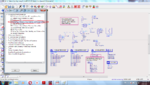
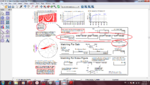
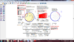
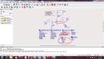
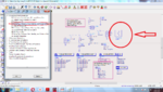
i tried to extract s parameters for bjt bfr96 amplifier for specific Q point(VCE=10V, IC=50mA) from s parameters simulation in ADS 2017 but it not as same as bfr96 datasheet.
i know the S Parameters from vendor datasheet is reliable, but what about the S parameter simulation???
thank you in advance!