Continue to Site

Welcome to EDAboard.com

Welcome to our site! EDAboard.com is an international Electronics Discussion Forum focused on EDA software, circuits, schematics, books, theory, papers, asic, pld, 8051, DSP, Network, RF, Analog Design, PCB, Service Manuals... and a whole lot more! To participate you need to register. Registration is free. Click here to register now.

Power topology selection for a 1W (12V to 140V) power converter design

Status
Not open for further replies.

bhl777

Full Member level 6
Joined
Sep 30, 2008
Messages
363
Helped
0
Reputation
0
Reaction score
0
Trophy points
1,296
Activity points
5,140
Hi All, I have an application that need to convert 12V DC to a 140V DC, by delivering 1W to the load. I want to pick up a suitable topology for this application, but I can only think of using flyback topology. Would anyone give me some advice if flyback is the most suitable topology? Thank you!
 

Since low power is needed, a boost converter should be adequate. It can be made with one inductor. A flyback is made with a transformer.
 

  • Like
Reactions: bhl777

    bhl777

    Points: 2
    Helpful Answer Positive Rating
Hi,

Conversion factor for the converter is 11+. That's pretty high you know. You cannot solely depend on duty cycle to achieve it.

You need a transformer to help step up the voltage. Since it is 1W, a flyback is your best bet.

There is a limitation to how much boost you can attain with Duty cycle alone. It depends majorly on your power stage resistances, especially that of the inductor winding and it's ratio to the load resistance.

Go for a flyback.
 
Last edited:
  • Like
Reactions: bhl777

    bhl777

    Points: 2
    Helpful Answer Positive Rating
It's true a flyback is better able to produce several watts, but in this case the load is spec merely 1W (load calculates as 19k ohms at 140VDC. So a boost converter does not require such an extreme duty cycle.

Admittedly there is the tradeoff decision to be made, whether to go for a larger Henry value, or a faster frequency. Strangely that is the convenient way to handle small current throughput in an inductor. (Whereas, if several watts were required, then it's feasible to have a smaller Henry value and slower frequency.)

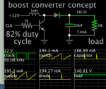
Demo boost converter, 12V to 140V 1W load. Duty cycle 82%. This allows ample Off-time remaining for the inductor to discharge a pulse of energy to the output stage.

boost converter clock-driven 50kHz 1mH npn 12V to 140 VDC 1W.png
 

Unfortunately, due to circumstances, I cannot run simulation at the moment.
...in this case the load is spec merely 1W (load calculates as 19k ohms at 140VDC.
Yes, load resistance is about 19kohm. That's a more-than-high-enough value for the load-resistance-inductor-winding-resistance ratio test actually. A boost converter might do, maybe.
Demo boost converter, 12V to 140V 1W load. Duty cycle 82%. This allows ample Off-time remaining for the inductor to discharge a pulse of energy to the output stage.

View attachment 151309
Maybe you should still model inductor winding resistance and switch Ron to double check. The duty cycle may go up significantly from the 0.8 value. You know the output peaks out at a duty cycle of about this value and then begins to dip as duty cycle is increased the more.
 
It's true a flyback is better able to produce several watts, but in this case the load is spec merely 1W (load calculates as 19k ohms at 140VDC. So a boost converter does not require such an extreme duty cycle.

Admittedly there is the tradeoff decision to be made, whether to go for a larger Henry value, or a faster frequency. Strangely that is the convenient way to handle small current throughput in an inductor. (Whereas, if several watts were required, then it's feasible to have a smaller Henry value and slower frequency.)

Demo boost converter, 12V to 140V 1W load. Duty cycle 82%. This allows ample Off-time remaining for the inductor to discharge a pulse of energy to the output stage.

View attachment 151309

Hi BradtheRad,

Thank you for your advice! I have one question regarding the safety requirement when I consider boost. Assuming boost will work fine, do you think it will be any safety issues to use the non-isolated boost converter? I heard that any applications with voltage higher than 60V should include the transformer to provde electrical isolation, is this a true statemet?

Thank you!
 

voltage higher than 60V should include the transformer to provde electrical isolation, is this a true statemet?

60V is about the voltage where it's a shock hazard to us.

If we operate a boost converter with no load and no safeguards, output voltage soars rapidly. It can reach levels which destroy components. One milli-Amp is able to stop our heart. Our body might conduct that much in contact with 140V.

Generally a transformer provides galvanic separation. This would supposedly protect your 12V circuit.

If you decide to build a flyback then your secondary should be wound with wire insulated to be safe for high voltage. If you always obey high voltage precautions then you can wind it with similar wire as found in small wall wart transformers. In fact your transformer might come from a wall wart. In reverse it steps up voltage.
 

Maybe you should still model inductor winding resistance and switch Ron to double check. The duty cycle may go up significantly from the 0.8 value. You know the output peaks out at a duty cycle of about this value and then begins to dip as duty cycle is increased the more.

Yes, if we try to get too much boost from a boost converter, then the duty cycle approaches 100%, leaving little time for the output (discharge) pulse.

I tried your suggestion, adding 3 ohms inline with inductor and 3 ohms inline with switch. This dropped output voltage several volts at 82% duty cycle. To get back to 140V I found it necessary to increase duty cycle to 88 %.
 

Status
Not open for further replies.

Similar threads

Part and Inventory Search

Welcome to EDABoard.com

Sponsor

Back
Top