id_ruben
Newbie level 4
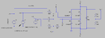
I got the scheme from a 380VAC voltage monitor, where the device has the ability to detect phase reversals and detect voltage levels.
https://drive.google.com/open?id=1HmntXd_m6UNQM8ECU9T4-cpuA9Jnm5lt
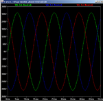
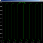
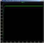
I have tried simulating in LTSPieceXVII and giving a 1.7V DC voltage to the output.
But I don't know how this circuit works and the formula is mainly on R1, R2 and C1.
Please help me about the workings of the circuit and formulas, so that I can determine the exact component value so that I can design the output of the tool that is in accordance with the ADC level (+ 5V).
I really appreciate every assistance given
thank you
https://drive.google.com/open?id=1HmntXd_m6UNQM8ECU9T4-cpuA9Jnm5lt
I have tried simulating in LTSPieceXVII and giving a 1.7V DC voltage to the output.
But I don't know how this circuit works and the formula is mainly on R1, R2 and C1.
Please help me about the workings of the circuit and formulas, so that I can determine the exact component value so that I can design the output of the tool that is in accordance with the ADC level (+ 5V).
I really appreciate every assistance given
thank you