Continue to Site

Welcome to EDAboard.com

Welcome to our site! EDAboard.com is an international Electronics Discussion Forum focused on EDA software, circuits, schematics, books, theory, papers, asic, pld, 8051, DSP, Network, RF, Analog Design, PCB, Service Manuals... and a whole lot more! To participate you need to register. Registration is free. Click here to register now.

The H Bridge can't simulation on Proteus

Status
Not open for further replies.

laoadam

Member level 2
Joined
Feb 22, 2019
Messages
52
Helped
0
Reputation
0
Reaction score
0
Trophy points
6
Activity points
324
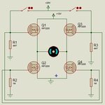
I made a simple 4x IRF3205 H Bridge for testing some thing out, the breadboard works well, but can't simulate on Proteus.
The schematic and error message attached, please help.
H Bridge T1 post.JPG
 

There's no error, just a warning.

- - - Updated - - -

There's no error, just a warning.

The gate voltage of high side transistors isn't appropriate for NMOS.
 

Hi,

It seems you don't understand how a Mosfet works.
ON/OFF depends on V_GS. G = gate, S = source.

In your schematic this means ALL resistors need to be connected to GATE and it's respective SOURCE.
To switch ON a Mosfet the GATE voltage (wrt GND) needs to be higher than SOURCE voltage (wrt GND).
This means: if you expect the HIGH side output voltage to be 12V(for example) then the gate voltage needs to be 20V (for example).

This is very basic, thus you can find this information in every basic N-Ch Mosfet halfbridge description.

Klaus
 

How do you guys read the tiny text on the fuzzy JPG image? On the other website I said it is because the schematic has its parts too far apart but I did not mention increasing the size of the schematic to see it covered with JPG fuzz.
 

Thank you all.
Yes, I'm no good at Mosfet. In fact, for this specific circuit, I did separate Power supply for Switches [P1] and MOSFETs [P2], no matter P1 and P2 equal or which one higher, the Proteus can t do situation in any configurations. But they all works on breadboard. Its. strange for me to post out.

- - - Updated - - -

How do you guys read the tiny text on the fuzzy JPG image? On the other website I said it is because the schematic has its parts too far apart but I did not mention increasing the size of the schematic to see it covered with JPG fuzz.

The clear circuit. H Bridge T2 post.JPG
 

Try installing high-ohm resistors between ground and each end of the load. Then the upper mosfets can have some definite path to ground. It's because the gate is referenced to the source terminal. For Nmos the source is conventionally connected to ground. At least that might create a simple arrangement that the simulator can calculate. With real hardware this is not necessarily an error.

The simulator may require the easier calculation how much current flows, as compared to the harder decision whether the mosfet turns on at all.

If you were to change the upper mosfets to Pmos then the simlation might run smoother. Turn them on by grounding the gate. Turn them off by applying supply voltage to the gate.
 

Hi,

V_GS of 20V is the "absolute maximum rating" not the "operational specification".

Example:
Let's assume it is a bungee rope.
It's specification says that it may break when the load is more than 80kg.
Would you use this rope when your weight is 80kg?

Klaus
 

Hi,

Your picture shows just two "messages", no warning, no error.
You don't show what is not like expected.

Still the drving circuit / driving voltages are not correct.
--> simply measure V_GS (voltage between gate and source) of each Mosfet in ON and OFF condition.

Your junction dots are weird. Some are correct, some are missing, some are where I don't expect one.

Klaus
 

Hi,

Your picture shows just two "messages", no warning, no error.
You don't show what is not like expected.

Still the drving circuit / driving voltages are not correct.
--> simply measure V_GS (voltage between gate and source) of each Mosfet in ON and OFF condition.

Your junction dots are weird. Some are correct, some are missing, some are where I don't expect one.

Klaus

Thank you KlausST, attached the picture shown the motor stationary no matter which switch turned on. and can you point out or correct the weird junction dots for me?
H Bridge T2 post.3.JPG
 

Use voltage and current probes to check yourself what's happening in the circuit.

- - - Updated - - -

You seem to have placed the GND symbols directly on the resistor terminals. They are probably not connected. Want to ask why I'm not using Proteus?
 

Use voltage and current probes to check yourself what's happening in the circuit.

- - - Updated - - -

You seem to have placed the GND symbols directly on the resistor terminals. They are probably not connected. Want to ask why I'm not using Proteus?

Thank you FvM,
The GND being reconnected nothing change.
The attached picture shown that:
1. simulation well done when removed two MOSFET;
2. the Vmeter shown not '0' when the switch open;
3. the 4 MOSFETs circuit still not be able to simulation.
H Bridge T2 post.4.JPG
 

Hi,

I wonder why you continously ignore to measure V_GS.

This makes it impossible for me to help you.

Klaus
 

The attached picture shown that:
1. simulation well done when removed two MOSFET;
2. the Vmeter shown not '0' when the switch open;
3. the 4 MOSFETs circuit still not be able to simulation.
Unfortunately the measurements can't be read. But there's obviously something wrong with your Proteus circuit.
 

Hi,

I wonder why you continously ignore to measure V_GS.

This makes it impossible for me to help you.

Klaus

Sorry KlausST, I just figure out where to put the Vmeter. The number is 4.18V.

- - - Updated - - -

Unfortunately the measurements can't be read. But there's obviously something wrong with your Proteus circuit.

Thank you FvM.
The reading in (A): 0.7V
The reading in (B): 20V
 

Hi,

--> simply measure V_GS (voltage between gate and source) of each Mosfet in ON and OFF condition.
A voltmeter has two connections.
And if you want to measure GATE to SOURCE voltage...
Then simply connect one voltmeter connection to GATE and the other voltmeter connection to SOURCE.

Sorry KlausST, I just figure out where to put the Vmeter. The number is 4.18V.
What (other) options do you see?

If V_GS really is 4.18V .. do you recognize that this means the Mosfet is neither fully ON nor fully OFF.
A situation you should avoid. Do you understand this?

I really recommend to read some basic tutorials...
* about voltage and current
* about voltage and current measurement
* basic transistor circuits and operation principles

There are many, many, even video tutorials, use them.

Klaus
 

Hi,


A voltmeter has two connections.
And if you want to measure GATE to SOURCE voltage...
Then simply connect one voltmeter connection to GATE and the other voltmeter connection to SOURCE.


What (other) options do you see?

If V_GS really is 4.18V .. do you recognize that this means the Mosfet is neither fully ON nor fully OFF.
A situation you should avoid. Do you understand this?

I really recommend to read some basic tutorials...
* about voltage and current
* about voltage and current measurement
* basic transistor circuits and operation principles

There are many, many, even video tutorials, use them.

Klaus

Thank you Klaus,
The readings from these few posts are relative to the half Bridge which CAN simulation.
Originally the post was talking about the H Bridge that can not be simulated by Proteus, any comment about ?
 

I see ground and supply icons placed at the middle of a wire. There is no dot to indicate a definite join. We can't be certain the supply and ground are connected.

Try placing the ground and supply at corners where two wires meet. I think a dot should appear then.
 

@ BradtheRad BradtheRad

Thank you BradtheRad BradtheRad.
I improved the connections and it CAN simulate now, but error message as attached, whats wrong?

H Bridge T2 post.6.JPG
 

Hi,

I assume the junction dots are at the correct places now.
How does your circuit look like, now?

I'm not experienced with proteus, but I assume there is a simulation setup.
* Variable voltage and current sources .... which parameters?
* simulation parameters like time step ...?
And so on..

Klaus
 

Status
Not open for further replies.

Similar threads

Part and Inventory Search

Welcome to EDABoard.com

Sponsor

Back
Top