Continue to Site

Welcome to EDAboard.com

Welcome to our site! EDAboard.com is an international Electronics Discussion Forum focused on EDA software, circuits, schematics, books, theory, papers, asic, pld, 8051, DSP, Network, RF, Analog Design, PCB, Service Manuals... and a whole lot more! To participate you need to register. Registration is free. Click here to register now.

Inverter based power on reset

Status
Not open for further replies.

deveshkm

Member level 4
Joined
Jul 18, 2017
Messages
71
Helped
0
Reputation
0
Reaction score
0
Trophy points
6
Activity points
615
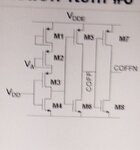
Why are two diode connected transistors used in inverter based Power on reset?
Reference: Low cost low power POR circuit for low voltage sensing using adaptive bulk biasing
Authors: Manoj Kumar Tiwari and Mohd Rizvi
2016 11th International Conference on Industrial and Information Systems
 

Hi,

do you want us to do an internet search? ... to maybe find the circuit you are talking about?

Why no link or a schematic?

Klaus
 

IMG_20190213_145538.jpg

PFA the screenshot of the schematic
 

Hi,

Maybe to create a voltage drop.
 

Seems like a crappy scheme to me, having designed many
PORs into production ICs. The first inverter will make the
second stage poorly driven and draw current full time, with
its value pretty variable.
 

Status
Not open for further replies.

Similar threads

Part and Inventory Search

Welcome to EDABoard.com

Sponsor

Back
Top