Continue to Site

Welcome to EDAboard.com

Welcome to our site! EDAboard.com is an international Electronics Discussion Forum focused on EDA software, circuits, schematics, books, theory, papers, asic, pld, 8051, DSP, Network, RF, Analog Design, PCB, Service Manuals... and a whole lot more! To participate you need to register. Registration is free. Click here to register now.

Open collector output arduino with led with PLC inputs problem

Status
Not open for further replies.

Big_Joe2

Newbie
Joined
Feb 11, 2019
Messages
3
Helped
0
Reputation
0
Reaction score
0
Trophy points
1
Activity points
29
Hello

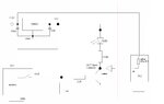
Please, let me know if the diagram is correct. Arduino hands out a transistor which in turn drives the input in the PLC. The PLC responds to a short to ground. The question is, why, despite the lack of the signal from andurino in the PLC, the entry at random moments is violated?

The LED is a need for optical control of the ardiuno output control. Transistor BC847.
The input data is a momentary / monostable signal with ardiuno, and "PLC" basically represents the alarm panel input which implements the bistable mode and switches on / off specific outputs after violation of the input. The problem is that occasionally the PLC controls the output despite the absence of a violation with ardiuno (the LED is off and the PLC informs about violation of the IN input).
 

Attachments

  • arduino_plc2.jpg
    arduino_plc2.jpg
    63.1 KB · Views: 156

Two potential issues:
1. the 'low' level at the PLC input cannot go lower than VCEsat + diode Vf. A Schottky diode would be more appropriate than a 1N4005.
2. if the PLC pulls up to +12 (as shown) it probably exceeds the PIV limit of the LED and could therefore perhaps not reach full 12V.

You could consider moving the LED to the output of the Arduino instead of the collector of the transistor.

Brian.


Is inserting a rectifier diode in series with a led to solve the problem?
 

Hi,

The series diode will at least safe the LED.

You say the PLC reports the violation.
This means the PLC (and not the LED or the arduino) sees the wrong voltage.
So the voltage may be
* too low
* too high
* or somewhere between valid low and valid high value.

A scope or a DVM could give clarification.

And the documentation of the PLC ... when/why the PLC sees a violation.

Klaus


Inserting a rectifier diode in series with led solved the problem.
I've been correcting the scheme, please let me know if I've chosen good LEDs

arduino_plc2_v2.jpg
 

Those parts should be OK but you can use a smaller Schottky diode if you like, it will only carry a few mA at most so a signal type rather than power rectifier could be used.

Brian.
 

Status
Not open for further replies.

Part and Inventory Search

Welcome to EDABoard.com

Sponsor

Back
Top