Continue to Site

Welcome to EDAboard.com

Welcome to our site! EDAboard.com is an international Electronics Discussion Forum focused on EDA software, circuits, schematics, books, theory, papers, asic, pld, 8051, DSP, Network, RF, Analog Design, PCB, Service Manuals... and a whole lot more! To participate you need to register. Registration is free. Click here to register now.

[SOLVED] AC/DC converter explaination

Status
Not open for further replies.
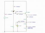
It neither works as a voltage reference if connected this way. Presently R3, D5, Q1 are useless and can be replaced by a wire powering the reference.

I really hate reverse engineering, you never know what the designer was thinking... I am afraid if i remove them i'd miss something
 

Hi,

I'm also curious as to why bother with a regulator after 40,000uF capacitance to remove voltage ripple. I only needed about 3,300uF for a 15V AC, 1A supply to considerably reduce the ripple, and I remember the ripple calculations resulted in diminishing returns regarding inrush current versus voltage ripple removal for even the 3,300uF.

Even I can see that that circuit is just a touch silly looking, if you don't mind. You can use a current source to power the TL431, the datasheet (that or the LM334 one) show the LM334 being used to provide a supposedly better current to the 431 than a resistor would, but as FvM has said - those components (R3, D5, Q1) are an "unusual configuration" for a current source. The Op Amp is serving as an error amplifier, so, again, you can just use the TL431 to serve that same purpose unless this is some high precision voltage regulator.
 

I'm also curious as to why bother with a regulator after 40,000uF capacitance to remove voltage ripple. I only needed about 3,300uF for a 15V AC, 1A supply to considerably reduce the ripple, and I remember the ripple calculations resulted in diminishing returns regarding inrush current versus voltage ripple removal for even the 3,300uF.

this is actually designed to supply 12A, it's also used for HiFi sound systems, it has to be extra pure, I am actually using 10000uF (75£ caps, audio grade) to get the best performance.

Even I can see that that circuit is just a touch silly looking, if you don't mind. You can use a current source to power the TL431, the datasheet (that or the LM334 one) show the LM334 being used to provide a supposedly better current to the 431 than a resistor would, but as FvM has said - those components (R3, D5, Q1) are an "unusual configuration" for a current source. The Op Amp is serving as an error amplifier, so, again, you can just use the TL431 to serve that same purpose unless this is some high precision voltage regulator.

It is actually high precision regulator, I am short on time and I am just trying to copy something that would definitely save me time and is proved to be working perfectly.

thanks for your help though, I will try changing the references and see how it goes.
 

Hi,

I just simulated it as the upside-down LED section got my curiosity and it does indeed appear to work extremely well with a 23V AC, 50Hz input. The upside down LED is odd.

...So that's the reason for so much capacitance, thanks. I'd wondered if it were a laptop supply. Is there no limiting resistor there? My simulation gave horrible +-20A swings from the supply, which is obviously not so in reality, surely.

Gosh, you're copying, that's cheating! ;) If you want to improve it, you could get rid of that trimpot if possible, I think they're supposed to be a weak link in circuits for temperature reasons.
 

I'd wondered if it were a laptop supply. Is there no limiting resistor there? My simulation gave horrible +-20A swings from the supply, which is obviously not so in reality, surely.

Well it actually feeds another board with a DC/DC converter to step it down to 12v, the current limiting stuff is there.

If you want to improve it, you could get rid of that trimpot if possible, I think they're supposed to be a weak link in circuits for temperature reasons.

this is one of the things i am trying to do actually. this is from a custom made power supply my client had from before.
 

Hi,

Thanks for explanations, much appreciated.

Couldn't resist reading a little... I didn't know that reverse breakdown voltage in LEDs is generically stated as 5V but some LEDs survive up to ~170V and that they have - theoretically - no accompanying leakage current. There are quite a few different forums where members have shared results and photos of their tests/experiments with reverse biasing a variety of LEDs to breakdown point but from my point of view it looked like no colour was predictably higher than any other, depends on LED technology. It seems that it's a safe approach, unless the 23V AC may suddenly swing far beyond that value or the LED is a runt from the production lot - very few suffer real reverse breakdown at 5V, apparently.

I was quite interested in what the LED's doing there, it was to get a stable Vbe, and a DC simulation shows these results:

thread regulator ccs LED DC simulation.JPG

I'm curious as to why the reference filter cutoff frequency is 23Hz rather than say 10Hz.
 

I think LED is used to detect reverse polarity, and prevent breakdown of Q1 base-emitter junction with reversed voltage. It is not useful to regulate the Veb, Q1 is in saturation normally, Vce is some mV.
Oh, sorry maybe above d123 has already said this.
 
  • Like
Reactions: d123

    d123

    Points: 2
    Helpful Answer Positive Rating
Status
Not open for further replies.

Similar threads

Part and Inventory Search

Welcome to EDABoard.com

Sponsor

Back
Top