Continue to Site

Welcome to EDAboard.com

Welcome to our site! EDAboard.com is an international Electronics Discussion Forum focused on EDA software, circuits, schematics, books, theory, papers, asic, pld, 8051, DSP, Network, RF, Analog Design, PCB, Service Manuals... and a whole lot more! To participate you need to register. Registration is free. Click here to register now.

High frequency coils, homogeneous B field

Status
Not open for further replies.

Salvador12

Full Member level 4
Joined
Jul 16, 2014
Messages
206
Helped
3
Reputation
6
Reaction score
7
Trophy points
1,298
Activity points
3,947
Hi folks can you help me out with this, So there is a circular surface area , actually two such areas , in my example the area is 25cm in diameter, I need to produce a homogeneous B field through that area (flux lines all pointing in the same direction) and I need to do it in the RF frequency range,

I thought about using Helmholtz coils as they are usually made from two separate coils and I could put each of the circular planes right next to each coil,

Now the problem probably is how to achieve strong enough B field at such high frequencies? The coils would probably have to be made from some single loop water cooled tube or something like that because the B field strength that I'm aiming for (well as strong as possible would be great) but realistically speaking about 0.2?? Tesla?

Also even though I have searched the internet it is complicated to find them all at once I probably need formulas to calculate the inductance and capacitance of the coils and the necessary capacitor to put in series to make them resonant in order to decrease the total inductive resistance and have higher current hence larger field .

Thank you.
 

Specifically what frequency are you aiming for? For anything I'd consider RF (>1MHz), 0.2T is incredibly strong. You're looking at hundreds of kW, at least. And the interference in nearby electronics will be tremendous, enough to be extremely hazardous to people with implanted electronics.

To give some background, the RF transmit field in an MRI scanner is around 20uT at 64MHz. This requires a >10kW RFPA, which is pulsed at low duty cycles. Even at that low field strength it's still a safety issues for patients in the scanner.
 

I will use a small sized mesh enclosure for the surroundings I just need to produce that field so that it runs through the circular plane which is part of an LC circuit forming an oscillator.

Well the frequencies could be in a wide range in the RF spectrum because I have an LC circuit and the field will go through the L part which has almost zero impedance (basically as much as that of a straight wire) and then for thew C part I have a variable capacitor so I could adjust it to suit the resonance of each frequency in a given range.
For test purposes probably I am looking at the lower end of RF to make matters easier and to reduce the problems associated with generating this B field through the Helmholtz coils.

I assume I would be better off by making the coils a series resonant LC with added cap and then determine the specific cap capacitance to match the coil inductance in order to get resonance and limit the impedance in order to get any decent amount of current through.
Any advice ?

thanks.
 

Have you done any calculations to estimate how many turns and amps you'll need to get 0.2T?

For example for a 25cm diameter loop of wire, you need about 40,000 amp-turns to get 0.2T in the center.

And "the lower end of RF" is completely meaningless. That could be 1kHz or 1GHz, depending on the context.
 

So there is a circular surface area , actually two such areas , in my example the area is 25cm in diameter,

Do you mean a hemispherical surface? Circle is a planar figure and 'circular surface' is confusing.

Or is it a plane surface with a circular boundary? Yes, Helmholtz's coils are ideal for this purpose. They are separated (centre to centre) by a distance equal to their diameter. The currents in each coil must be in the same direction.

With such an arrangement, the magnetic field is uniform at the cenrre (yes, it is homogeneous at one point only). Now you need to calculate the field strength and the frequency of operation.

One Tesla is quite a strong magnetic field and you will need lots of ampere-turns. because your coils are 25cm in diameter (or area??), you may perhaps need to use insulated copper pipes (instead of wires).

If you are planning to use high frequencies, you may have no other option but to use a single turn coils. (but that depends)...

You want the magnetic field for 1s? 1ms? or for DAYS>>>

Working at RF frequencies for a magnetic field (0.2T) is not going to be cheap.
 

I meant a circular 2d surface parallel top the coils like imagine a disc being put perpendicular at the end of the coil,

I was thinking the upper Khz region lower Mhz region. But isnt it the case that for the Mhz frequencies as the wavelengths become smaller the helmholtz coil if sufficiently large in diameter wont work anymore? In other words I wont be able to make a uniform homogeneous field at or between the coils?

yes mtwieg I plugged in some numbers and it seems that for an air core (since no other material fits the bill at high frequency) coil in order to achieve any meaningful B field strength either I need resonance and lots of current or without resonance even more current and high voltage in the end tremendous power.
Buy how do you think even if all other aspects can be made t work how strong of a field I could realistically get by using some copper water tubes with water cooling at resonance?
 

I mean the surface is parallel to the coils, like does anyone have anything to add ?
 

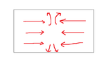
Does anybody know of a RF cavity like the TEM cell where the B field would look something like this? please view the attached image edaboard cell.png

because I get the feeling that with Helmholtz coils I will not be able to practically achieve either high enough frequency or high enough B field strength at high frequency.
 

If you feed your pair (of Helmholtz) of coils current in the opposite direction, the field will appear like the one you have drawn. The field at the centre will be zero.

Lines of forces need to be smooth. So, if you draw your diagram neatly, you find that the field at the centre vanishes.
 

I know that it vanishes at the center and that's ok I need the field to be homogeneous and strong right next to each coil where the perpendicular planar surface will be located.

the problem is how do I get a strong enough field , also from helmholtz coils there will be alot of emitted radiation and energy losses , RF cavities like the TEM cell seem to be better at that point, but can they have a field like this in any configuration?
 

Helmholtz coils have the wire turns one on top of the other.
https://www.3bscientific.com/imagelibrary/U21901/U21901_01_Helmholtz-Coils-on-Mounting-Plate.jpg

I think better are planar coils (with turns side by side) as the ones used in inductive wireless power transfer systems. The drawback of these systems is they need ferrite plates (or ferrite bars) placed under the coil, to increase the radiated field.
But in this way you can get huge amount of radiated field from relative small diameter coils.
https://pdfs.semanticscholar.org/44ee/4834df3fab49958525c5673ba6e623216a54.pdf
 

Status
Not open for further replies.

Part and Inventory Search

Welcome to EDABoard.com

Sponsor

Back
Top