Continue to Site

Welcome to EDAboard.com

Welcome to our site! EDAboard.com is an international Electronics Discussion Forum focused on EDA software, circuits, schematics, books, theory, papers, asic, pld, 8051, DSP, Network, RF, Analog Design, PCB, Service Manuals... and a whole lot more! To participate you need to register. Registration is free. Click here to register now.

Far Field - Linear Virtual Array 2TX 8RX

Status
Not open for further replies.

Luca_Romano

Junior Member level 2
Joined
Apr 24, 2015
Messages
21
Helped
0
Reputation
0
Reaction score
0
Trophy points
1
Activity points
219
Dear all,

I have a doubts regarding the far field formula (R_far_field = 2D²/λ) in the case of virtual array configuration (as illustrated in the attached figure).
Which value I should consider as D? (82,136 mm?). The antenna front end is used in a FMCW radar in 77-79 GHz band.
Thanks a lot in advance,
Best regards,
L.R.
Immagine1.png
 

In antenna arrays the far field D is the distance between the farthest antennas which are part of the array.
In your case (where you have two antennas, RX and TX) D would be 29.220mm for the RX antenna, and 29.250mm for the TX antenna.
Each antenna will have its own far field, which starts at about 240mm for each antenna (at 77GHz).
 

Hello vdfone,
thanks a lot for your reply. I still have doubts, please correct me if I'm wrong:
  • don't we have to take into account that we're using a virtual array? do we have to consider only the phisical array? The resulting virtual array in the case I presented here is made by 32 virtual elements (it's a TDM system, one by one the TX antennas are activated while all RX antennas receive simultanesily).
  • Each antenna will have its own far field, which starts at about 240mm for each antenna (at 77GHz).
    here you mean each group of antennas (RX and TX ones). But don't I have to consider the far field of the two TX antennas separetely? the TX antennas are not irradiating at the same time but one at time.
    Far field at 240mm it corrisponds to have D around 21.6 mm, which D did you consider ?
  • I'm wondering about the correct far field distance because I'm using the radar to evaluete a layer size as shown in the following figure and I notice that the profile of the soil and of the top of the layer is really so curved. I'm using a 2D FFT, maybe it is not the good processing choice if we are not in far field?!
    Immagine2.jpg
Thanks a lot again,
Best Regards,
LR
 

Sorry, wrong math. The far field of each antenna is about 438mm, which makes each antenna to be in the near field of the other antenna.
If the RX and TX antennas not working in the same time why you need to take into consideration the virtual antenna?
 
Hello vfone, sorry for the late replay.
If the RX and TX antennas not working in the same time why you need to take into consideration the virtual antenna?
The RX antennas and one TX antenna (per time) are working in the same time. I was wondering about the far field of the virtual array (created thanks to the TDM) because I'm processing all the 32 virtual antennas received data.
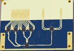
Here you find the antenna front end, this is used in a radar system.

antennavirtual.JPG

- - - Updated - - -

I have seen it, it helps but not so much; I would avoid to use any subspace based method.
For single TDM step (one patch activated) i would use single patch far field. How exactly do you use R_far_filed in your calculations? Do you perform any windowing before FFT?
I'm not using the R_far_field value in my calculations, I was wondering about it because I noted that the radar image is so much distorted; I thought because the targets were not in far field zone...but now I think that is not the real problem.
 

In my opinion, the problem may be because of improper signal processing. The easiest way to know for sure is comparing results with some commercial product which performs similar task. Ensure that signal processing is correct. I would use 1D FFT for each antenna IQ output in TDM step and retrieve phase information. Then I extract distance/angle information for different pairs of antennas with simple monopulse processing. Windowing of input signal is pretty important to obtain good phases and amplitudes which are not jumping around due to signal discontinuity at the edges of data window. Using this data it is possible to build 2D map similar to what you showed above. Then using this viewer app i would go through different pairs of antennas and build 2D maps and see if those maps looks greater than your current result.

I almost sure that there is a problem with signal processing. How exactly do you use 2D fft currently, maybe some reference to a paper?
I see a problem here: lets take two adjacent leftmost RX channels, and two adjacent rightmost RX channels. Using 4x 1D FFT we may obtain 2D maps for leftmost and rightmost antenna pairs. To combine this 2D maps to a focused 2D map distance between antenna pairs must be taken into account. As we go further through all antenna combinations there always be some offset. And this offset increases for close reflectors.
So your 2D FFT algorithm must take two effects into account:
1. 2D map generated using antenna pair have an offset (distance between RX antenna array center and midpoint between antenna pair)
2. 2D map generated using antenna pair have different angle scale based on distance between antenna pairs.
if these effects are not compensated, then combined 2D map will be unfocused
 

Hello Georgy,
thanks for your reply and interest in the topic.

I almost sure that there is a problem with signal processing. How exactly do you use 2D fft currently, maybe some reference to a paper?
The 2D FFT processing is pretty simple, the following reference explain the procedure:
"S. M. Patole, M. Torlak, D. Wang, and M. Ali. Automotive radars: A review of signal processing techniques. IEEE Trans. Acoust., Speech, Sig. Proc., 34(2):22–35, 2017."
Below the code section I'm using for the FFT processing only:
Code:
   % DataV  is the single sweep time/spatial samples arranged in a [N_antennas x N_samples] matrix 
   % the others parameters are about the FFT order, the scale factor the calibration matrix to correct the phase shifts (due to rf circuitry, etc) 
   % I tried a lot of windowing options to reduce the sidelobes (here i'm using a hanning win)   
    
    % Calculate range profile including calibration 
    RP          =   fft(DataV.*Win2D.*mCalData,NFFT,1).*Brd.FuSca/ScaWin;
    RPExt       =   RP(RMinIdx:RMaxIdx,:); 

    % calculate fourier transform over receive channels
    JOpt        =   fftshift(fft(RPExt.*WinAnt2D,NFFTAnt,2)/ScaWinAnt,2);
        
    % normalize cost function
    JdB         =   20.*log10(abs(JOpt));
    JMax        =   max(JdB(:));
    JNorm       =   JdB - JMax;
I see a problem here: lets take two adjacent leftmost RX channels, and two adjacent rightmost RX channels. Using 4x 1D FFT we may obtain 2D maps for leftmost and rightmost antenna pairs. To combine this 2D maps to a focused 2D map distance between antenna pairs must be taken into account. As we go further through all antenna combinations there always be some offset. And this offset increases for close reflectors.
So your 2D FFT algorithm must take two effects into account:
1. 2D map generated using antenna pair have an offset (distance between RX antenna array center and midpoint between antenna pair)
2. 2D map generated using antenna pair have different angle scale based on distance between antenna pairs.
if these effects are not compensated, then combined 2D map will be unfocused
 

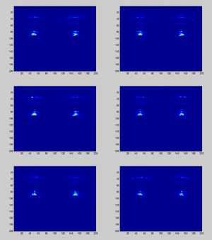
I did some processing on Luca's data, here is animation. Left part is for TX1 on, right part is for TX2 on.
I expected to see horizontal lines too, but instead there are several radial curves.
Idea N1:Maybe reflections from soil in broadside direction are strongest, and FMCW seep is not very steep, so distance resolution is not enough to represent enough points with different distances (FFT bins) from the soil to the radar antenna.
Idea N2: On some frames you may see kind of weak horizontal lines. It is possible that soil reflection is weak, which results in large phase errors of my simplistic FMCW monopulse processing.
Idea N3: Another possibility is if single channel ADC slowly multiplexed to 16 channels and introduces progressive phase shift (unlikely).
attachment.php
 

Attachments

  • radarv2.gif
    radarv2.gif
    112.8 KB · Views: 222
Last edited:

Update: I have checked my idea on antenna pair offsets and came to conclusion that effect is negligible.
Distance to first soil reflection is more than 1 meter, and ~ 29 mm offset between leftmost and rightmost antenna pairs do not contribute much to monopulse angle error.
I moved reflectors on map along x axis according to formula (for 16 antennas):
Code:
xFix=distScale* ( halfLambda*ind1 +(halfLambda)*(ind2-ind1)/2 -  7*halfLambda );
ind1, ind2 - antenna pair indexes
Effect is negligible, but visible.

Made few alterations to algorithm and achieved much better radar map image:
attachment.php
 

Status
Not open for further replies.

Part and Inventory Search

Welcome to EDABoard.com

Sponsor

Back
Top