Continue to Site

Welcome to EDAboard.com

Welcome to our site! EDAboard.com is an international Electronics Discussion Forum focused on EDA software, circuits, schematics, books, theory, papers, asic, pld, 8051, DSP, Network, RF, Analog Design, PCB, Service Manuals... and a whole lot more! To participate you need to register. Registration is free. Click here to register now.

How this circuit works

Status
Not open for further replies.

ku637

Advanced Member level 4
Joined
Apr 6, 2011
Messages
116
Helped
2
Reputation
4
Reaction score
3
Trophy points
1,298
Activity points
2,551
Hello ,

Can some one help me understanding how this circuit functions? Basically the emitter terminal of T2 is used as a power supply in an application circuit.(I have shown like 12k ,as current requirement is low)

Is this a darlington pair arrangement? R2 15k confuses me.. Can some one explain how it is working?
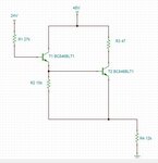
bjt.JPG

Sorry there has been a mistake .. both the supplies are 24V only no 48V in the system..forgive the mistake in figure..
 
Last edited:

  • Like
Reactions: ku637

    ku637

    Points: 2
    Helpful Answer Positive Rating
Is this a darlington pair arrangement?
Yes.
R2 15k confuses me..
Why, base-emitter pull-down resistor is even built-in with many power darlington transistors, review datasheets. Its purpose is also reduction of leakage current.
 
  • Like
Reactions: ku637

    ku637

    Points: 2
    Helpful Answer Positive Rating
Thank you for the input.. what can be the purpose of 47Ohms any suggestion? is it to limit the output drive current?
 

Thank you for the input.. what can be the purpose of 47Ohms any suggestion? is it to limit the output drive current?

Yes. Probably the only purpose.
 
  • Like
Reactions: ku637

    ku637

    Points: 2
    Helpful Answer Positive Rating
Status
Not open for further replies.

Similar threads

Part and Inventory Search

Welcome to EDABoard.com

Sponsor

Back
Top