Continue to Site
Follow along with the video below to see how to install our site as a web app on your home screen.
Note: This feature may not be available in some browsers.
Experimentally, bias the AF input transistor from the wiper of a potentiometer, adding a 1K series resistor in the base to protect it. It will not be reliable but it should prove the principle.
Brian.
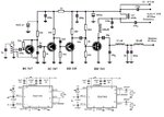
Like this Brian?I would take the top of the potentiometer to 12V. You want the emitter of the modulator to have around 6V on it so the base should be ~0.6V higher than that. Bear in mind that if you assume it will pass around 1A, the base current will be as much as 40mA (based on minimum HFE) so its bias resistor can be no higher than (12-6.6)/.04 = 135 Ohms. With 1K it's no wonder it doesn't work well!
Brian.
That is correct, you can probably change the 100R to 150R to save a little current. I based the maximum value of the data sheet minimum HFE but in all probability the HFE will be higher than that. Note the polarity of the input capacitor, the base will never have more than +0.6V on it so be careful of any DC voltage present on the audio input.
Brian.
")
That isn't strictly true but in practice it sometimes helps to modulate more than one stage. The danger is that by feeding the driver stage from a modulated supply, it starts to change the load on the oscillator and introduce FM, the overall result may be worse. You could try it and if the carrier frequency shifts by more than say 100Hz, add an additional buffer stage between oscillator and driver, powered from the regulated supply. Checking for FM should be easy, just monitor the carrier frequency and turn the pot from end to end to simulate minimum and maximum PA load.They say there is something about solid state finals and class C that keeps them from 100% modulation.
With Bipolar transistors, a percentage of the input drive power appears in the output.
Which means that the driver stages must also be modulated.