Continue to Site

Welcome to EDAboard.com

Welcome to our site! EDAboard.com is an international Electronics Discussion Forum focused on EDA software, circuits, schematics, books, theory, papers, asic, pld, 8051, DSP, Network, RF, Analog Design, PCB, Service Manuals... and a whole lot more! To participate you need to register. Registration is free. Click here to register now.

Core material for current transformers

Status
Not open for further replies.

Jester

Full Member level 6
Joined
Aug 18, 2012
Messages
377
Helped
7
Reputation
14
Reaction score
7
Trophy points
1,298
Location
.
Activity points
4,754
Magnetics is definitely a weak point for me, I need some help, hopefully someone with expertise can offer some guidance.

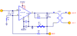
I'm using an audio amplifier configured as a current source for some testing I'm doing. It works well, however this amplifier is limited to about 3Arms @20V. I would like to increase the current capability for testing and hope to use a current transformer (about 3 or 4:1), to increase current while loosing compliance voltage. I have this working using a fairly large 100:5 window CT that I happened to have laying around, using 2 turns through the window, I can deliver 13Arms into a very low burden. I was aiming for 10A, so the concepts seems sound, I just need a more compact CT.

Today I found some smaller 250:5 CT's (2VA), however I think 2VA is really marginal for anything other than a dead short, so I'm considering winding a CT to try and optimize size and capability. From the little I have read, CT's operate with minimal flux compared to a power transformer and therefore require different (possible better) core materials. Can anyone suggest a source in USA/Canada for toroidal cores that would be suitable, and a particular core if possible?

10VA if it can be accommodated with :
- Finished diameter should be 3-4"
- Can be up to 3" thick
- 10Arms from 2.5Arms from the amplifier

Ideal actual # of turns?

If you need more details just ask.

Thanks
 

Measurement current transformers have specific requirements, particularly high µr to reduce the error due to magnetizing current.

As far as reported, your application doesn't impose these specific requirements, it sounds like a regular audio transformer problem. Frequency range and transferred power are the relevant parameters for core selection, in case of doubt a regular transformer core would be a good choice. Nothing against a toroidal core in general, but it sounds like a way to make your life harder than necessary.
 
  • Like
Reactions: Jester

    Jester

    Points: 2
    Helpful Answer Positive Rating
Hi,

If the CT is in the feedback path of an audio amplifier, then a passive CT won't work, because it is not abke to feedback DC.
Thus you should expect DC runaway.

There are active current sensors, they can work with DC. They use "compensation" technique. The primary current causes a magnetic field it is compensated by the active secondary side.

Klaus
 
  • Like
Reactions: Jester

    Jester

    Points: 2
    Helpful Answer Positive Rating
Measurement current transformers have specific requirements, particularly high µr to reduce the error due to magnetizing current.

As far as reported, your application doesn't impose these specific requirements, it sounds like a regular audio transformer problem. Frequency range and transferred power are the relevant parameters for core selection, in case of doubt a regular transformer core would be a good choice. Nothing against a toroidal core in general, but it sounds like a way to make your life harder than necessary.

I will try a regular power transformer, I should have a 120:24 in my transformer box.

- - - Updated - - -

Hi,

If the CT is in the feedback path of an audio amplifier, then a passive CT won't work, because it is not abke to feedback DC.
Thus you should expect DC runaway.

There are active current sensors, they can work with DC. They use "compensation" technique. The primary current causes a magnetic field it is compensated by the active secondary side.

Klaus


Tha audio amplifier is configured as a current amplifier, amp -> CT -> current sense resistor -> Gnd. The voltage at the CSR provides feedback to the amplifier. This seems to work fine @ 60Hz
 

Hi,

I can't see how the load is connected.
A sketch could clarify...

Klaus
 

I should have a 120:24 in my transformer box
20:5 volts would be optimal.

The voltage at the CSR provides feedback to the amplifier. This seems to work fine @ 60Hz
AC only feedback is of course possible, if combined with respective DC stabilization.
 
  • Like
Reactions: Jester

    Jester

    Points: 2
    Helpful Answer Positive Rating

Attachments

  • ISRC.png
    ISRC.png
    36.9 KB · Views: 142

I see. A primary current sense can work for DC to operation frequency.

I read post #4 so, that the current sense should be performed on the transformer secondary, which is apparently Klaus' understanding in post #3 as well.

Secondary current sense has the advantage of compensating the transformer magnetizing current, but need to be bypassed for DC and possibly for high frequencies, too.
 
  • Like
Reactions: Jester

    Jester

    Points: 2
    Helpful Answer Positive Rating
20:5 volts would be optimal.

AC only feedback is of course possible, if combined with respective DC stabilization.

I'm going to keep looking for a suitable power transformer, everything I have found so far with high output current capability (10A) is well over 10VA, most of them 150VA, which is too large for the space I have available.
 

Your specification demands 50 VA @ 60Hz transformer size, can be reduced to 42.5 VA by choosing an autotransformer configuration.
 
  • Like
Reactions: Jester

    Jester

    Points: 2
    Helpful Answer Positive Rating
Your specification demands 50 VA @ 60Hz transformer size, can be reduced to 42.5 VA by choosing an autotransformer configuration.

Can you explain how you calculated 50VA?

I’m looking for 1V @ 10Arms to the load.
 

You didn't specify a load impedance thus I put in the amplifier output voltage. But if you are sure about 10 A @ 1V...
 
  • Like
Reactions: Jester

    Jester

    Points: 2
    Helpful Answer Positive Rating
Hi,

I read post #4 so, that the current sense should be performed on the transformer secondary, which is apparently Klaus' understanding in post #3 as well.
Yes. This is what I thought

Klaus
 

Status
Not open for further replies.

Part and Inventory Search

Welcome to EDABoard.com

Sponsor

Back
Top