Continue to Site

Welcome to EDAboard.com

Welcome to our site! EDAboard.com is an international Electronics Discussion Forum focused on EDA software, circuits, schematics, books, theory, papers, asic, pld, 8051, DSP, Network, RF, Analog Design, PCB, Service Manuals... and a whole lot more! To participate you need to register. Registration is free. Click here to register now.

Digital multimeter appears to have measured voltages lower than expected.

Status
Not open for further replies.
T

treez

Guest
Hi,
I have just measured a load of DC voltages on the 200mV range of the handheld XL830L multimeter.
Its just occurred to me that the readings all appear to be some 10% lower than they should be.
Do you know what the input resistance of the XL830L is when on the 200mV range? Its datasheet doesn’t say.
XL830L meter
https://usefulldata.com/wp-content/uploads/2015/09/Excel-XL830L-Multimeter-Instructions-manual.pdf

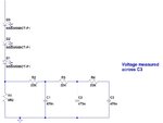
By the way, the voltage readings were taken downstream of an RC filter consisting of a 66 kiloOhm resistor and 470nF capacitor. (ie taken across the 470nF cap). The origin of the voltage was current flowing through a 0R22 resistor.

++++++++++++++++++++++++++++++++++++++++
Also, on a separate note, please could you confirm that a digital multileter, even if damaged, would never be likely to actually supply current into a node that it was measuring the voltage of. (and thus make that voltage appear higher than it was)
 

Megohms per volt is a usual input spec for meters. You
could of course measure with a second meter, to know
for sure what you're dealing with.

DMMs can give squirrely results on DC when there's AC
content. You might try a good meter with true-RMS and
compare results.


But there is also the question of the soundness of your
"should be" belief.
 
  • Like
Reactions: treez

    T

    Points: 2
    Helpful Answer Positive Rating
Its just occurred to me that the readings all appear to be some 10% lower than they should be.

It reminds me the old perverb:

A man with a watch knows what time it is; but a man with two watches is never sure.

The natural question: in a static circuit, measurement of voltage across a capacitor is never reliable. You are essentially shorting the cap with a 10M load.

Basically you are measuring the voltage across a voltage divider of 66K and 10M (not so sure about this one).

Do you have any AC ripple voltage? That can make life hell. But 10% less with respect what? Expected or simulated value?
 
  • Like
Reactions: treez

    T

    Points: 2
    Helpful Answer Positive Rating
Thanks, the circuit being measured is as attached.
The current in the 0R22 resistor is half sine "humps" at 10ms period and peak of around 1.7A.
(current in the 0R22 is always only in one direction, just fluctuating)
 

Attachments

  • Voltage measurement.jpg
    Voltage measurement.jpg
    52.7 KB · Views: 216

Hi,

From your posts:
1)
Its just occurred to me that the readings all appear to be some 10% lower than they should be.
2)
(current in the 0R22 is always
3) But the picture shows 0.2 Ohms, which is 10% lower than 0.22 Ohms.....

Klaus
 
  • Like
Reactions: treez

    T

    Points: 2
    Helpful Answer Positive Rating
sorry that was a mistake, i do apologise...it is 0r22 in the real circuit.
The problem is that the XL830L DMM doesnt state its input impednace in its datasheet i think, do you know it?
 

Like others, I expect 10 M input resistance. But it's easy to measure, isn't it?
 
  • Like
Reactions: treez

    T

    Points: 2
    Helpful Answer Positive Rating
The current in the 0R22 resistor is half sine "humps" at 10ms period

That makes it AC plus DC. And your filter is good for small signal; can it take power surges of 1.7A?

I find the AC component troubling. You can be better off with a scope.
 
  • Like
Reactions: treez

    T

    Points: 2
    Helpful Answer Positive Rating
Like others, I expect 10 M input resistance. But it's easy to measure, isn't it?
Thanks, i thought some of the cheap meters, due to their inclusion of protection circuitry to protect against connection to overly high voltages, end up with much lower input impedance.
But yes, i believe we can measure the Zin by setting up a divider of 10Meg---10Meg, and then measring the voltage across the lower 10Meg, and seeing what that voltage comes out as.

I think the cheap meters are only meant for measuring low impedance source voltages such as batteries or outputs of power supplies etc, so suspect their Zin will be low, because its cheaper to make them so(?)
 

I think the cheap meters are only meant for measuring low impedance source voltages such as batteries or outputs of power supplies etc, so suspect their Zin will be low, because its cheaper to make them so(?)
Only analog meters. The way digital ones work means the input impedance is fairly constant across all ranges and is usually at least 10M on DC and usually AC ranges.

Brian.
 
  • Like
Reactions: treez

    T

    Points: 2
    Helpful Answer Positive Rating
Analog meters operate on armature current so must have
an input impedance low enough to take some.

Digital meters are generally capacitive ADC front ends and
pull no DC current (quality scatter / leakage aside). The
input network only needs to provide any restoring charge
for the capacitor shuttle charge, within the clock cycle
(which is pretty slow). 10Mohm resistors cost the same as
10Kohm, divider taps on a ladder that's fixed makes input
jack impedance constant-enough.
 

Why dont you just take two known resistors, make a voltage divider, and verify that your crappy $9 meter is working properly?
 

I think the cheap meters are only meant for measuring low impedance source voltages such as batteries or outputs of power supplies etc, so suspect their Zin will be low, because its cheaper to make them so(?)

Only analog meters. The way digital ones work means the input impedance is fairly constant across all ranges and is usually at least 10M on DC and usually AC ranges.

Brian.

Not necessarily.
Analog meters can also contain input amplifiers that boost the input impedance so that it can be in range of mega or giga ohms.
 

Many guesses, little knowledge.

As previously reported, almost all cheap digital multimeters have 10 Mohm input impedance for AC and DC voltage ranges. It's specified in more detailed operation manuals. High impedance "electrometer" inputs are optionally exposed by bench top multimeters, for obvious reasons usually only with lower voltage ranges up to 10 or 20 V.
 

If it has an Amplifier in it, It will also have a Battery.
 

Search " review of xl830l - lygte info".
 
  • Like
Reactions: d123

    d123

    Points: 2
    Helpful Answer Positive Rating
Any multimeter that has resistance ranges, will also have
a battery even if there is no front end amplifier.
 

Why dont you just take two known resistors, make a voltage divider, and verify that your crappy $9 meter is working properly?

What do you mean by "known resistors" ?
All of them have some tolerance so it's pointless. On top of that, do you know the exact value of the voltage source you use for this ?
To make it work you will need precise voltage reference and resistors with tolerance of 0.1%. The other way is to get precise voltmeter and compare its reading with the tested one.
 

What do you mean by "known resistors" ?

get a 1.5 volt cell and note down the voltage.

get two 1M and two 10M resistors; 1% resistors will be enough. You can make do with 10% resistors too.

measure the cell voltage with 1M in series and also with 10M in series. Note down the values.

now connect two 1M resistors in series and across the cell. measure the voltage across the resistors.

repeat the same with the 10M resistors in series. record the voltages.

now you can explain the difference.
 

This is still invalid - no matter what resistors you use or a cell; you are unable to determine if the voltmeter works properly. It may have some offset and be non-linear due to poor quality of its input circuitry or damaged components. Besides, its input impednce may change depending on the range used. It's much better option to borrow the multimeter from your friend and just compare to the one you test.
 

Status
Not open for further replies.

Part and Inventory Search

Welcome to EDABoard.com

Sponsor

Back
Top