Continue to Site

Welcome to EDAboard.com

Welcome to our site! EDAboard.com is an international Electronics Discussion Forum focused on EDA software, circuits, schematics, books, theory, papers, asic, pld, 8051, DSP, Network, RF, Analog Design, PCB, Service Manuals... and a whole lot more! To participate you need to register. Registration is free. Click here to register now.

Possible Signal Integrity problem in a 100MHZ CLK

Status
Not open for further replies.

flote21

Advanced Member level 1
Joined
Jan 22, 2014
Messages
411
Helped
1
Reputation
2
Reaction score
3
Trophy points
1,298
Activity points
5,595
Hello guys,

I am wondering about a signal integrity issue with a 100MHz clk generated by an FPGA.

This is the set up:

- FPGA generates a 100MHZ square signal with 50% of duty cycle.
- The IO constraint is LVCMOS 3.3V.
- The PCB track has a length of 20cm and it finished in a Sub-D25 connector. The track has a series termination resistor (Rt).

In the next pic you can see the problem:
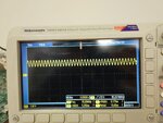
photo_2018-12-14_08-07-27.jpg

It does not matter the value of the Rt, the CLK signal always looks like that. So it has a 1.5V offset and it has an amplitude around 800mV.

What do you think it is happening? I should set up a special constraint in the FPGA side to get this clock like a square signal with an amplitude of 3.3V?

Greetings
 

Hi,

That is why one creates impedance controlled traces.
Without knowing the parameters for your trace impedance it's hard to help. (Trace width, GND plane, PCB material, thickness...)

You say there is a series termination resistor. But no value. Does it match the trace impedance?

The DSUB most probably is not the "end" of the signal. Thus it makes not much sense to measure the signal there.
Install the circuit at the other side of the DSUB, with proper termination. Then do the measurement again.
Be careful ... that your scope probe does not harm the signal.

There may be other issues. Like not suitable scope probe (impedance, bandwidth...) or wrong scope setup (bandwidth limitation)...

Without complete informations it's hard to help.

Klaus
 

Beside all other possible problems, you need an oscilloscope with 500 MHz, better 1 GHz bandwidth and a suitable probe (active or resistive) to reproduce a 100 MHz square wave.
 

Hi! Thanks for your answer. There is a 0hm series termination resistor, and the Trace is routed with Zo=50ohm. I tested a 47ohm series termination and the waveform almost doesn't change.
On the other hand, I have also connected the device to the SubD-25 and the aspect of the waveform doesn't change either...

- - - Updated - - -

The oscilloscope should not be the problem because its characteristics are 100MHz and 1Gs/s

- - - Updated - - -

I have also tried to measure a 120MHz square signal in other track and I was able to see a perfect square signal with the same oscilloscope...
I am a bit lost right and I don't know what else can I try...
 

That doesn’t make sense. You can’t see a square 120mhz signal with a 100Mhz scope since the square has many higher harmonics.

Note that 100mhz bandwidth means even a 100Mhz sin wave will be attenuated substantially.
 

Ok. Maybe it was with other model of oscilloscope. But I checked a 80MHz signal with this one I have observed the same attenuation and the same Offset as the 100MHz signal... what do you think about it?
 

Hi,

80MHz square wave is built from a lot of sinewaves (overtones, read about fourier series):
240MHz, 400MHz, 560MHz, 720MHz, ...


100MHz square wave is built from a lot of sinewaves (overtones):
300MHz, 500MHz, 700MHz, 900MHz, ...


You see, even the first overtone is at 240MHz or 300MHz respectively.....
For a square wave to "almost look like a squarewave" you need at least the 10-fold bandwidth than it's fundamental frequency.

Klaus
 
totally understood. I need a faster OC to see a perfect square signal. But what about the offser? Why is it having a 1.8V offset? It is also because the OC is very slow to sample that signal?

Thanks in advance...

Greetings
 

The oscilloscope is showing the expectable average DC value of a 50% 3.3V square wave quite nicely, 1.65V
 
Hi,

Today I did the same measure with another oscilloscope: 500MHz of Bandwith and I have seen the same waveform....
 

Hi,

OK, then do another measurement:
* use the high speed scope
* use the high speed probe: select 1:10
* connect probe_GND next to the FPGA
* connect probe to the FPGA-Pin with the 100MHz output ... (as close as possible to the FPGA, best directly at the FPGA pin)

Take a photo oft the scope picture including scope setup.

***
May I ask why we don´t see exactly 100MHz? it´s just about 96MHz.

Klaus
 

It looks like one of the signals in a differential LVDS pair.
I think you accidentally have activated a differential driver.
 

Status
Not open for further replies.

Part and Inventory Search

Welcome to EDABoard.com

Sponsor

Back
Top