Continue to Site

Welcome to EDAboard.com

Welcome to our site! EDAboard.com is an international Electronics Discussion Forum focused on EDA software, circuits, schematics, books, theory, papers, asic, pld, 8051, DSP, Network, RF, Analog Design, PCB, Service Manuals... and a whole lot more! To participate you need to register. Registration is free. Click here to register now.

A general question about optoisolators and EMI

Status
Not open for further replies.

doncarlosalbatros

Full Member level 2
Joined
Nov 26, 2016
Messages
143
Helped
1
Reputation
2
Reaction score
1
Trophy points
18
Activity points
1,758
This is a conceptual question about opto isolators couplers and their use in pulse or digital signals.

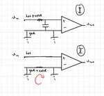
In a single ended transmitter receiver system for digital signals if the noise is at the signal line(hot), then low pass filter is used to mitigate the noise as in Figure 1 below:
9AC6C186-95B5-43FE-A417-8750B6887B17.jpeg

In such system if there is EMI or a noise that would also bounce the ground RC filter will not help since the noise is also at the ground line as shown in red loop in Figure 2 above.

Are opto isolators used in such cases? Is the idea to break the loop and prevent the EMI to induce a looping current?

Im trying to understand why or when the opto isolators should be used and how does it prevent the interfernce caused noise.
 

I'm not quite sure I understand your question. Are you talking about common-mode noise? If so, the optoisolator can actually be thought of as a differential input device, and thus, common mode noise will be cancelled.
 

You would start with a reasonable equivalent circuit of an opto isolator. The shown three pin device obviously isn't.
 

Have a look at the way MIDI ( music interface stuff) and its opto-isolators are connected, with gounding at one end only.
 

You would start with a reasonable equivalent circuit of an opto isolator. The shown three pin device obviously isn't.

I didn't draw an opto isolator. In Figure 2 Im imagining EMI is hitting through radiation or conduction to both lines.
Yes I think EMI is always common mode interference.

I was wondering why the inference does not occur after the optoisolator.

- - - Updated - - -

I'm not quite sure I understand your question. Are you talking about common-mode noise? If so, the optoisolator can actually be thought of as a differential input device, and thus, common mode noise will be cancelled.

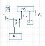
Yes I meant EMI common mode interference. For example recently I had such issue:

KgeML.jpg

I was looking for a possible way to eliminate such spike only at node X which is caused by EMI.
The thing is in such cases I also need a another power supply at the other side of the opto.
And the opto's output wires will be long like 100cm. Since I cannot put the supply very local to the output. Should I use STP cables after the opto in that case?

Im sorry maybe this is not related to this question but Im a bit desperate to find a hint about these.

- - - Updated - - -

This lead me to another issue which is totally different question https://www.edaboard.com/showthread...r-power-supply-not-local-with-an-optoisolator

Thanks.
 

Isolation does a number of things. One is that it lets you split a large system into isolated pieces and keep the noise generated in each piece to itself. Second it lets your system be immune to that noise.
 

I didn't draw an opto isolator. In Figure 2 Im imagining EMI is hitting through radiation or conduction to both lines.
Yes I think EMI is always common mode interference.

I was wondering why the inference does not occur after the optoisolator.
Drawing the real optocoupler with usually two input and two (or three) output pins would be the first step to achieve an understanding.
 

Status
Not open for further replies.

Part and Inventory Search

Welcome to EDABoard.com

Sponsor

Back
Top