Continue to Site

Welcome to EDAboard.com

Welcome to our site! EDAboard.com is an international Electronics Discussion Forum focused on EDA software, circuits, schematics, books, theory, papers, asic, pld, 8051, DSP, Network, RF, Analog Design, PCB, Service Manuals... and a whole lot more! To participate you need to register. Registration is free. Click here to register now.

Need help checking the schematic

Status
Not open for further replies.

Magdy_said

Newbie level 6
Joined
Sep 28, 2018
Messages
12
Helped
0
Reputation
0
Reaction score
0
Trophy points
1
Activity points
151
i was making a simple buck converter using an AVR as a controller and 6n137 optocoupler as a highspeed isolator

datasheet : https://pdf1.alldatasheet.com/datasheet-pdf/view/30862/TOSHIBA/6N137.html

and in last minute after i bought the chip just discovered that the output voltage is only 5 volts and i need 10 volts to drive the mosfet irf3205, if i drived it with Vgs = 5v the R on will be so high (i think) and there will be more losses in the converter so i decided to add another irf 3205 but i am not sure of what i am doing. can you help me and give it a check?

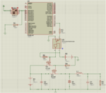
first design :
u10.png

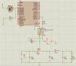
second design :

u11.png

- - - Updated - - -

edit : i just realized that Vgs on n fet won't be enough so if replaced Q1 in first design with a p channel mosfet and lowered the 1 k resistor to around 500 to optimize the time constant, it should work perfectly right?
 

Re: need help checking the schematic

If you have insufficient drive voltage to turn one MOSFET on, it will still insufficient to turn two on.

You can do it with a bipolar transistor as the MOSFET driver or consider an alternative opto-coupler that can withstand higher output voltage.

Brian.
 

Re: need help checking the schematic

Non of the designs will work.

To turn a NMOS switch fully on, the gate voltage must swing above the drain voltage. BUK455 is a standard MOSFET which needs Vgs of 8 - 12 V to turn it fully on. 12 - 15V Floating gate driver supply referenced to MOSFET source would be the standard solution. You also need driver push pull capability with impedance in the 10 ohms range. An opto isolated gate driver like TLP450 can be a solution.
 

Re: need help checking the schematic

I would answer to the edited question: PMOS control voltage is 0V to 5V, but if you connect the PMOS source to 12V how will you close the device? 5V gate voltage won't be enough to close it down, you should convert the optocoupler's output to a higher voltage level. A simple amplifier on the 12V supply could do that.
 

6N136 has a logic output driver Frankrose. It's open collector but has an absolute maximum 'pull-up' to 7V so it can't be used directly in that schematic. It still needs something to raise the voltage or make the driver stage accept TTL levels.

Brian.
 

Well,

I think that bootstrapping is necessary. You need to find a way to drive the MOSFET with a voltage referenced to the diode-inductor node. The differential voltage needs be enough to drive the FET though.

Add:
A simple highside driver and a bootstrap circuit should do.

Add:
See this application note "AN-6076 Design and Application Guide of Bootstrap Circuit for High-Voltage Gate-Drive IC" from ON Semiconductor.

- - - Updated - - -

Your exact case is the Floating Supply Gate Driver on page 11.
 
Last edited:

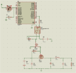
ok, while i was i figured another configuration it just simple modification i hope it work, Q1 is IRF5305 p channel mosfet Vgs1 need to be 12 or 0 and this the job of Q2 n channel , Q2 is controlled by the opto with 5 volts on so Q2 won't be completly open but will deliver the required volt to Q1, it won't matter if Q2 has a relativly high resistance,right?

u12.PNG
 

PMOS switch is a simple solution. 300 ohm is a bit weak driver and causes respectively slow turn-off and switching losses. One would prefer a push-pull driver in this place.

Another point is purpose of opto isolator. It makes no sense if both circuits use same ground as in your schematic.
 

Status
Not open for further replies.

Similar threads

Part and Inventory Search

Welcome to EDABoard.com

Sponsor

Back
Top