Continue to Site

Welcome to EDAboard.com

Welcome to our site! EDAboard.com is an international Electronics Discussion Forum focused on EDA software, circuits, schematics, books, theory, papers, asic, pld, 8051, DSP, Network, RF, Analog Design, PCB, Service Manuals... and a whole lot more! To participate you need to register. Registration is free. Click here to register now.

[AWR Microwave Office ] Impedance of parallel connection of transmission lines

Status
Not open for further replies.

Eres_89

Member level 1
Joined
Jul 11, 2012
Messages
34
Helped
0
Reputation
0
Reaction score
0
Trophy points
1,286
Activity points
1,651
Hi All,

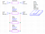
in last time, I'm confused due to some simulations in the AWR Environment. I've connected three TLs as a parrarel configuration, and I measured the total impedance of such circuit. According to circuit theory, and my knowledge - I should obserce impedance equal to Z0=Z_TL/3 - so in case presented bellow - it should be Z0 = 2.481 ohms. Unfortunatelly, AWR is showing Z0=0.8428ohm... Proper value can be observed only when port impedance is divided by number of TLs (i.e. 3) - so then the port impedance is equal to 16.67 ohms, NOT to 50 ohms.


E. connection.png

Why is this hapen ? Must I consider changes of port impedance to measure "real" value of connection in this case ?

Best Regards,
E.
 

What do you mean with "total circuit impedance"? How do you measure it?

I think, your assumptions about the observed impedance are wrong. If the transmission lines are not terminated with their characteristic impedance, they transform the load impedance to a different value depending on the electrical length.
 

By the term "total circuit impedance" I had in mind resultant resistance of presented configuration.

I understand your thoughts (I hope so...), that in such case TLs are working as impedance transformers. So maybe I'll ask about other thing - how should I measure the resultant impedance in AWR Office ? On this moment, I'm using ZIN measurement. Below I'm sending next schematic of circuit constructed under mentioned environment. The independent TL has characteristic impedance Z0=30 ohms. I'm assuming that, for resonant frequency (where electrical length is equal to 90 degrees), such element is working as a resistor. So parallel connection of three elements must give value of Z_All=10 ohms, and I notice this value only when impedance of ports is decresed by number of TLs (port impedance is equal to 50/3 ohms).

I'm confused about this fact, because I know that you are right with transforming, but I don't see straight the solution why I must divide port impedance to have proper value according to Ohm's law...

test.png
 

Your independent TL Zo is not 30 ohms, but it is 39 ohms.
And I think that for your test you have to make the lines 180 degrees long, instead of 90 degrees.
 

I get impedance of 30.5 ohm with simple and 38.6 with more trustworthy tools.

In any case you get maximal transformation with 90 degree electrical length. 50 ohm is transformed to about 3.4 ohm by 13 ohm (39/3) transmission line.
 

Circuit theory is not applicable in this case where you talk about waves and not signals. You should study on the concept of "characteristic impedance"

"By the term "total circuit impedance" I had in mind resultant resistance of presented configuration. "

You are trying to use Norton and Thevenin circuit models when dealing with waves. Circuit Theory, Wave Theory and Microwave Theory apply under different conditions. First step is, knowing which one to use in the right environment.
 

Thank You for all sugestions and answers.

I forgot about one important thing, that the ZIN measurement in AWR is measuring input impedance of lines (from port side)... so mentioned 30 ohms is input impedance, not characteristic one... (if I'm wrong - correct me). FvM you have absolutely right.

So a new question arises: how can we calculate mathemtically total input impedance of such configuration - I mean - how we can calculate impedance which is seen on port 1 or 2 ?
I used following conception:
1) Take ZIN values of TL1, TL2 and TL2
2) Calculate characteristic impedances of them (Z01=sqrt(ZIN1*50), and so on)
3) Calculate resultant impedance ZR according to the Ohm law (ktr - yes, I know that we shouldn't use this conception from circuit theory, so here I've first main issue)
4) Calculate output impedance by using impedance from 3) i.e. Zout = (ZR^2)/50 - here we should have final value of such connection (and here is probably another issue)

Is there a simple explanation how to approach it?
 

so mentioned 30 ohms is input impedance, not characteristic one...
Why? Value of 39 ohm is characteristic impedance calculated according to TL geometry, parallel circuit has 13 ohms respectively.

If the observed impedance is different from calculated 3.4 ohm value, the electrical length is probably not 90 degree.
 

I see. FvM, vfone thank you for help.

I'm now wondering how it will be work, when lines will create a coupled structure. I know that the odd-even mode analysis can be used, but as I know such method is related only to circuits which have symmetry (so 2,4,6, etc. lines), so how discussed three line coupled structure can be considered ?
 

I understand that the lines in the original example are uncoupled and have equal length. In this case, the impedance is simply divided.

I don't see coupled lines specified in the circuit example. However, if a structure has symmetrical coupling, it will only expose its common mode impedance and not behave different than the uncoupled.
 

I'm now wondering how it will be work, when lines will create a coupled structure. I know that the odd-even mode analysis can be used, but as I know such method is related only to circuits which have symmetry (so 2,4,6, etc. lines), so how discussed three line coupled structure can be considered ?

Generally, you want to use multiconductor transmission-line theory to model arbitrary coupled lines. The modes can be determined, but are based on geometry. Clayton Paul's textbook is the cannon in this field.
 

Status
Not open for further replies.

Part and Inventory Search

Welcome to EDABoard.com

Sponsor

Back
Top