Continue to Site

Welcome to EDAboard.com

Welcome to our site! EDAboard.com is an international Electronics Discussion Forum focused on EDA software, circuits, schematics, books, theory, papers, asic, pld, 8051, DSP, Network, RF, Analog Design, PCB, Service Manuals... and a whole lot more! To participate you need to register. Registration is free. Click here to register now.

[SOLVED] P-mos not turning off.

Status
Not open for further replies.

tiwari.sachin

Full Member level 6
Joined
Aug 1, 2009
Messages
341
Helped
3
Reputation
6
Reaction score
3
Trophy points
1,298
Location
India
Activity points
4,449
Hi everyone,
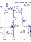
PFA image. The p-mos(U1) remains OFF initially when n-mos(Q1) is OFF. Once, a signal from n-mos(Q1) is sent, the p-mos(U1) turns ON, but, even after turning OFF the n-mos(Q1), p-mos(U1) remains ON. Can anyone say me the reason.., is this because of the capacitors connected to the "24V_mech" line ?? should I change the value of the capacitors??. The p-mos circuit(U1) works fine when it is not connected to "24V_mech" line i.e, it turns ON & OFF for similar signals from n-mos(Q1).
 

Attachments

  • power section.JPG
    power section.JPG
    28.5 KB · Views: 132
  • capacitors.JPG
    capacitors.JPG
    25.2 KB · Views: 103
  • capacitors2.JPG
    capacitors2.JPG
    49.2 KB · Views: 108

Hi,

When false_on.
Measure:
V_gs and V_ds of each mosfet with a DVM.
Show us these 4 values.

Klaus
 

I would additionally check for a shorted MOSFET. Charging 2000 uF without current limiting can easily damage the FET switch.
 

Hi klaus,

measure:
for nmos: when false on: Vg=0V, Vs=0V, Vd=24V,
when false off: Vg= 3.3V, Vs=0V, Vd=24V.
for pmos: when false on: Vg=30mV, Vs=300mV, Vd=24V,(initial conditions, didn't try to turn on and then turn o0ff)
when false off: Vg=24V, Vs=24V, Vd=24V

- - - Updated - - -

Hi,

The MOSFET is working fine.
 

A "false off" condition isn't mentioned in the previous posts. No idea what it means.

As for "false on". You report Vd(NMOS)=24V and Vg(PMOS)=30mV, which isn't possible with the shown circuit. Most likely the gate isn't correctly connected to the drive point (R1/R2 junction).

- - - Updated - - -

The reported "false off" condition suggests that also Q1 isn't correctly soldered to the circuit.
 

yes, there was a connection issue. The measures are as follows,
p-mos false on: vg=24V, Vd=0.5V, Vs=24V.
n-mos false on: Vg=3.2mV, Vs=0.5V, Vd=24V.

- - - Updated - - -

yes, there is a load, but the discharge process is too slow.
 

Hi,

False-ON usually means V_DS is low.
With both your Mosfets this isn't the case.

So why do you call it false-ON?

*********
BTW:
I asked you to measure V_GS and V_DS....but you measure all signals with respect to GND.
(Mind: A Mosfet has no dedicated GND pin, it only has G, D, S and thus no voltage given in a Mosfet's datasheet are w.r.t. GND)
To minimize errors I strongly recommend to measure the voltages directly at the Mosfet pins and not referenced to GND.

Klaus
 

Hi,

False-ON means that the MOSFET is OFF right??

If that is the case then these are the values,
p-mos: Vds=-23.72V, Vgs=0V.
n-mos: Vds=24V, Vgs=3.2mV.

If MOSFET is ON then these are the values,
p-mos: Vds=0V, Vgs=12V.
n-mos: Vds=3.3mV, Vgs=3.3V.

if the p-mos Drain is not connected to 24V_mech line(as shown in circuit) then the MOSFET is working fine, so should I make changes in the capacitors value??
 

Hi,

False-ON means that the MOSFET is OFF right??
No. "False ON" means the MOSFET is (false) ON where it should be OFF.

p-mos: Vds=-23.72V, Vgs=0V.
-->Correct MOSFET OFF function.

n-mos: Vds=24V, Vgs=3.2mV.
-->Correct MOSFET OFF function.

p-mos: Vds=0V, Vgs=12V.
-->Correct MOSFET ON function.

n-mos: Vds=3.3mV, Vgs=3.3V.
--> depends on MOSFET type. For usual MOSFETs V_GS = 3.3V is too low to be (saturated) ON. Read MOSFET datasheet.


Klaus
 
yes, there was a connection issue. The measures are as follows
p-mos false on: vg=24V, Vd=0.5V, Vs=24V.
n-mos false on: Vg=3.2mV, Vs=0.5V, Vd=24V.

yes, there is a load, but the discharge process is too slow.
The measurement is indicating "correct off" rather than "false on".
Means the problem is rectified and the thread should be marked as solved?
 

Hi,

How can I change the rate of discharge ? The discharge process should be quit fast. Should I change the value of capacitors? If so, what should be the nominal value?
 

Hi,

tau = R x C
To decrease tau you just have to decrease R or decrease C.

Klaus
 
There will be probably load current through J9 which isn't yet specified. It's useless to discuss the question without this information.

If there's no relevant load current, you may want to think about an active discharge circuit, NMOSFET + discharge resistor. The discharge resistor can be implemented as PTC for overload protection in case of switch failure.
 
Status
Not open for further replies.

Similar threads

Part and Inventory Search

Welcome to EDABoard.com

Sponsor

Back
Top