Welcome to our site! EDAboard.com is an international Electronics Discussion Forum focused on EDA software, circuits, schematics, books, theory, papers, asic, pld, 8051, DSP, Network, RF, Analog Design, PCB, Service Manuals... and a whole lot more! To participate you need to register. Registration is free. Click here to register now.
Re: How to drive cut of frequencu formula for attached LC filter circuit?
If you're in real life you simulate it and look at the graph (ltspice ac sim)
If you're in academia and want to 'cheat' use 'sapwin' which will solve the circuit for you in the S domain and give you the algebraic expressions for it.
Re: How to drive cut of frequencu formula for attached LC filter circuit?
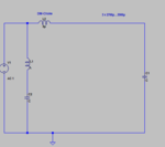
You have no damping, so instead of cutoff frequency, you have a peak that shoots up to infinity at the frequency you would have the cutoff frequency=1/2*Pi*sqrt(L2*C1) of a damped filter.
(no output is shown by the OP, however, the only 2 possible outputs across C1 or C2 have the exact same formula, obviously with alternate "C" and "L" value).
Re: How to drive cut of frequencu formula for attached LC filter circuit?
Hello all,
It is kind of redundancy circuit. The output will be taken across C1 and it would be given as input to one switching regulator.In the same way C2 output will be connected to another Switching regulator.
Hence i would like to theoretically calculate the cut off frequency of this circuit.
You have no damping, so instead of cutoff frequency, you have a peak that shoots up to infinity at the frequency you would have the cutoff frequency=1/2*Pi*sqrt(L2*C1) of a damped filter.
(no output is shown by the OP, however, the only 2 possible outputs across C1 or C2 have the exact same formula, obviously with alternate "C" and "L" value).
Thanks for the feedback. I would like to understand how this formula had been arrived. As i know if it single LC low pass filter then the cut off frequency formula can be derived by equating XL=XC and finally we get Fc=1/2*pi*sqrt(LC).. In this same way how the above formulas can be derived?
Re: How to drive cut of frequencu formula for attached LC filter circuit?
As LvW pointed out this circuit probably has an error. You have multiple parallel circuits attached to one ideal source. The two LC's therefore have zero interaction with one another. You could delete L1/C2 and it has no impact on the transfer function to C1 (try it). And vise versa.
Hence the math is just the simple formula for a single LC.
This site uses cookies to help personalise content, tailor your experience and to keep you logged in if you register.
By continuing to use this site, you are consenting to our use of cookies.