Continue to Site

Welcome to EDAboard.com

Welcome to our site! EDAboard.com is an international Electronics Discussion Forum focused on EDA software, circuits, schematics, books, theory, papers, asic, pld, 8051, DSP, Network, RF, Analog Design, PCB, Service Manuals... and a whole lot more! To participate you need to register. Registration is free. Click here to register now.

repurpose Power Relay from other circuit

Status
Not open for further replies.

Thayne

Member level 3
Joined
Apr 28, 2018
Messages
60
Helped
1
Reputation
2
Reaction score
1
Trophy points
8
Activity points
637
I have an old, discontinued, Zone Control Module from a former radiant floor heat system that I want to re-purpose for use of the power relay. My plan is to send a signal to the power relay from an ESP32. I have the power relay datasheet and think it will work for my project. I don’t want to desolder the power relay from that circuit board in case I use it later for something else.

Sorry if this is a dumb question… How can I hook the ESP32 to the board and then to an appliance? Is it possible?


Thanks! IMG_20181123_153233.jpg
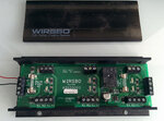
 

I have an old, discontinued, Zone Control Module from a former radiant floor heat system that I want to re-purpose for use of the power relay. My plan is to send a signal to the power relay from an ESP32. I have the power relay datasheet and think it will work for my project. I don’t want to desolder the power relay from that circuit board in case I use it later for something else.

Sorry if this is a dumb question… How can I hook the ESP32 to the board and then to an appliance? Is it possible?


Thanks!View attachment 150216

There's already circuitry attached to the relay, but you don't want to disconnect that, you just want to add your drive to it? Despite your apology, that sounds like a a dumb question. You don't even show what the existing circuitry is, which makes it impossible to give you an answer - a picture of the circuit board is useless.
 
  • Like
Reactions: d123

    d123

    Points: 2
    Helpful Answer Positive Rating
I can't find a schematic of the board. I found out the board was discontinued a long while ago. I found a diagram of a similar board by this company, but it is basically less helpful than looking at this board. I was hoping someone with HVAC experience could help. It looks like the three thermostats would plug in the top terminals and the devices that turn on and off would plug into the bottom terminals (one beneath each thermostat). The power comes in and out from the side(s). I don't know this for a fact. That is just my best guess.

Thanks
 

Try searching " cdam chapter 14 electrical schematics". Should give you a good idea of its original operation.
 

Try searching " cdam chapter 14 electrical schematics". Should give you a good idea of its original operation.

That is almost it. The diagram I have is not as good as that one, in terms of similarity. I think this one you found is close enough I can figure it out. Thank you!
 

Status
Not open for further replies.

Similar threads

Part and Inventory Search

Welcome to EDABoard.com

Sponsor

Back
Top