Continue to Site

Welcome to EDAboard.com

Welcome to our site! EDAboard.com is an international Electronics Discussion Forum focused on EDA software, circuits, schematics, books, theory, papers, asic, pld, 8051, DSP, Network, RF, Analog Design, PCB, Service Manuals... and a whole lot more! To participate you need to register. Registration is free. Click here to register now.

RF Distribution Project (need some advice! )

Status
Not open for further replies.

Simmiz

Newbie level 5
Joined
Mar 2, 2018
Messages
9
Helped
0
Reputation
0
Reaction score
0
Trophy points
1
Activity points
112
Hi guys!!
I'm trying to design a RF distribution for my wireless receivers.

I'm a sound recordist working in TV, so I have to deal with wireless microphones daily.
Basically the setup I would like to have is 2 dipole antennae connected to my 2 wireless receivers. I'm pretty good with a soldering iron and confident about SMD.

First open question ; Any advice for this setup? Does and don't ?

2nd question ; I've made a graph for every parts that would suits my needs, for example 20 different model of baluns/filters/power divider from mini-circuit that would work with my project. Some have lower insertion loss, but higher input return loss, Xphase unbalance, Xamplitude unbalanced, how do I tell which element is the most critical and that I need to watch for for this particular application?

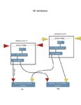
I've made a schema to give you an idea of what I'm trying to do.

Thank you so much guys you are awesome! I'm new to this as you can see..

rf-distro-smlr-png.png

[found at https:// ibb.co/fh51Zq]
 

Attachments

  • rf-distro (1).jpg
    rf-distro (1).jpg
    44.5 KB · Views: 143
Last edited by a moderator:

Now depends by the distance what you have between antennas. For good diversity performance the distance should be greater than λ/2.
I see your setup proposal, but I think that if you connect the distribution box1 only to RX1, and distribution box2 only to RX2, the diversity performances will be the same.
 

Thank you for your reply. Each receiver has to be connected to 2 separated antennae, so I could not connect both antennae of 1 receiver to a single dipole. Each receiver has antenna-A and antenna-B, what I'm trying to achieve is to sum the 2 A-antenna and the to B-antenna together via a distribution box.

Any cues about the parts?

Thank you!
 

You used Baluns at the input of the boxes, are your signal sources differential ?? If they aren't, the proposal will not work.
You have to use in this case combiner because balun is used to combine 2 differentially identical ( so phase difference must be 180 degree) signal sources.
 

Thanks for your reply, I've been told that since I use single conductor coax I must put a balun right after the antenna to connect the dipole, which is a balanced device to my coax which is unbalanced. Maybe there is a detail here I don't totally grasp. So I need to use a combiner that will sum the arms of the dipole into a single signal that will pass through the rest of the chain?
Regards,
Simon
 

Thanks for your reply, I've been told that since I use single conductor coax I must put a balun right after the antenna to connect the dipole, which is a balanced device to my coax which is unbalanced.

Simon, your approach with the balun is correct.
 
  • Like
Reactions: Simmiz

    Simmiz

    Points: 2
    Helpful Answer Positive Rating
Thanks for your reply, I've been told that since I use single conductor coax I must put a balun right after the antenna to connect the dipole, which is a balanced device to my coax which is unbalanced. Maybe there is a detail here I don't totally grasp. So I need to use a combiner that will sum the arms of the dipole into a single signal that will pass through the rest of the chain?
Regards,
Simon

I tought that they are signal sources.If they are dipole antenna, it's OK. The signals will be differential by nature..
 

Perfect.
Any cues regarding the specs of each part? Is it more important to have a lower input return loss or a lower phase unbalance?

- - - Updated - - -

Mini-circuits makes 20+ combiners that suits my needs, I don't know what I should look at into the specs. Most important is low input return loss? Isolation? Phase unbalance? Amplitude unbalance?

https://www.minicircuits.com/pdfs/ADP-2-9+.pdf
https://www.minicircuits.com/pdfs/JPS-2-1W.pdf
https://www.minicircuits.com/pdfs/ADP-2-1W+.pdf
https://www.minicircuits.com/pdfs/JPS-2-900.pdf
https://www.minicircuits.com/pdfs/ADP-2-4+.pdf

And then I've got the same amount of choices between baluns!
 

Mini-circuits makes 20+ combiners that suits my needs, I don't know what I should look at into the specs. Most important is low input return loss? Isolation? Phase unbalance? Amplitude unbalance?

I would go for the devices that are easily available. The small performance differences are not relevant for your needs, and might translate into only a few perfect range difference. The dipole isn't perfectly matched to 50 Ohm, so input return loss isn't very critical.
 
  • Like
Reactions: Simmiz

    Simmiz

    Points: 2
    Helpful Answer Positive Rating
May I ask why 400-700MHz bandpass filter?
 

Newbie question here

Disclaimer ; If you tend to be annoyed by lack of knowledge, please scroll on! I am a sound engineer, I have very limited knowledge in RF and analog circuits. I try to read and watch tutorials, but I get lost very quickly as I don't speak the basics of this language.

The project ; I am building a small 2 way distribution box for my 2 wireless microphone receivers.

Path ; Dipole antenna -> Balun -> 2 way Power Splitter - 2X female SMAs output -> wireless receivers.

The question ; I know this is elementary school for most of you, I just need someone to point me out which pins to connect where.

I got myself a mini-circuit 1:1 transformer and a 2 way power splitter. I am good at soldering, but I just don't know technically how to connect everything.

Here is my thinking, please tell me where I am wrong.

So we start with the 2 Dipole elements, one goes in the Primary of the balun, the other one goes in the secondary.
At the other side of the balun, Primary Dot becomes my main "signal", Secondary Dot connects to ground of the hole circuit.
Then my main signal enters the "S" port of the splitter, and the splitter is attached to ground that carries the signal from the other sides of the dipole (?)
Then at the exit of the Splitter, I attach 2 SMAs, that are grounded as well.

Here below the schematic of my 2 units.

Thank you so much for your help, it is very much appreciated.

https://imgur.com/a/UKALki2

https://imgur.com/a/YezoLGL
 

Status
Not open for further replies.

Part and Inventory Search

Welcome to EDABoard.com

Sponsor

Back
Top