Continue to Site

Welcome to EDAboard.com

Welcome to our site! EDAboard.com is an international Electronics Discussion Forum focused on EDA software, circuits, schematics, books, theory, papers, asic, pld, 8051, DSP, Network, RF, Analog Design, PCB, Service Manuals... and a whole lot more! To participate you need to register. Registration is free. Click here to register now.

Simple phasing SSB modulator demodulator does not work

Status
Not open for further replies.

neazoi

Advanced Member level 6
Joined
Jan 5, 2008
Messages
4,119
Helped
13
Reputation
26
Reaction score
15
Trophy points
1,318
Location
Greece
Activity points
36,918
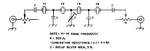
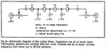
Hi, here is a bare bones SSB modulator/demodulator
rtty50.jpg
Tested by VK3YE at his page http://home.alphalink.com.au/~parkerp/projects/projssbphasing.htm (4th video down the page)

I tried to build it but it does not work. Even if I fed a high signal at the input of the transformer I get very very little increase in the carrier. none of the three port seems to respond to any settings.

I have used the same AF transformer with the 2K CT connected as shown. I figured out the 2K winding with a multimeter, which showed a DC resistance of 120 ohms if I remember well.
The DC resistance at the 10K end was around 600 ohms.
I used 1n5712 diodes instead
For the output transformer I used 4 turns on the diode side and about 30t or so for the output side, wound onto a T50-2

Any help please what to do?
 
Last edited:

As far as I can tell, the diodes are OK but I have doubts about the input capacitor values. I think they should be the same value to avoid LF phase differential at the mixer.

Bear in mind you should NOT get any output until audio is fed in. The potentiometers are there to null any residual carrier. Also bear in mind that it is designed for very narrow frequency use with only (probably) 170Hz difference in input audio tones. It is DSB, not USB as can be seen in the spectrograph. If you want SSB you have to filter out one of the sidebands.

Brian.
 
  • Like
Reactions: neazoi

    neazoi

    Points: 2
    Helpful Answer Positive Rating
As far as I can tell, the diodes are OK but I have doubts about the input capacitor values. I think they should be the same value to avoid LF phase differential at the mixer.

Bear in mind you should NOT get any output until audio is fed in. The potentiometers are there to null any residual carrier. Also bear in mind that it is designed for very narrow frequency use with only (probably) 170Hz difference in input audio tones. It is DSB, not USB as can be seen in the spectrograph. If you want SSB you have to filter out one of the sidebands.

Brian.

This is supposed to be an SSB modulator/demodulator, not a DSB.

I am sure the audio input network is too simplified and cannot correctly generate +/-45 degrees at all audio frequencies.
Also I am not sure how to swap sidebands, just swap the outputs of the input AF network to the diodes?

But first of all I have to make it work.
The input AF caps are made unequal in both the schematics I have seen. It is intended to generate +/-45 degrees of AF signals at the outputs maybe this is why they are made unequal?

Any more suggestions to try, to see why it does not work?
 

Any of those phasing SSB approaches are such complicate to build and to tune (phase AND amplitude), that barely worth to spend time on them.
A diode DSB (double side band) modulator followed by a cheap ladder crystal filter would work with decent performances right from the start, with a minimum of tuning. And the SSB signal will be steady whatever hoarse voice you have or how loud you speak into the microphone.
 
  • Like
Reactions: neazoi

    neazoi

    Points: 2
    Helpful Answer Positive Rating
Any of those phasing SSB approaches are such complicate to build and to tune (phase AND amplitude), that barely worth to spend time on them.
A diode DSB (double side band) modulator followed by a cheap ladder crystal filter would work with decent performances right from the start, with a minimum of tuning. And the SSB signal will be steady whatever hoarse voice you have or how loud you speak into the microphone.

That's true.
The problem is the building of a crystal filter, with so many parameters individual to each crystal, you have to have a good bunch of them and design a specific filter for them. A KIT form would be a nightmare to produce.

I like this network because it is bidirectional and requires minimum of components. The worst case opposite sideband rejection is about 20dB when tuned, and the response is not the same at all frequencies, but the worst case is 20db. I could live with that in a simple homebrew gear if I do not have to build this complex crystal filter.

The problem is that I still can't make it work, despite others have!
 

Making a 4 pole crystal filter, which gives at least 40dB side band suppression, its easy and really cheap. Use trim capacitors (and trim resistors for in/out resistance) to tune the filter. You need only a good receiver to listen the SSB signal. Most probably the tuning doesn't take more than few minutes.
The main rule to get a good SSB ladder crystal filter, when you don't have adequate test equipment to measure it (e.g. VNA), is to choose crystals with frequency lower than about 5MHz (3.57MHz, 4.000MHz, 4.43MHz, 5MHz, etc). Those crystals, even they are from different manufacturers, they have pretty close characteristics, which is a requirement for ladder filters.

Thanks for this last hint!
Do you think it could it be done with 6MHz as well, as I have lots of them?

So just using a filter design from the internet and placing random crystals will do the job? Is it really that easy?
 

Indeed, is that easy to make a decent ladder crystal filter for SSB without having fancy test equipment. For CW filters is even easier.

On the net are tons of schematics, papers how to do it, or online calculators.
https://www.giangrandi.ch/electronics/crystalfilters/xtalladder.html
https://www.changpuak.ch/electronics/Quartz_Crystal_Filter_Designer_2.php
**broken link removed**

6MHz crystals already enter in a different category for crystal qualification. If you don't have proper test equipment to measure the filter, stay on crystals below 5MHz. But if you have a lot of them, doesn't cost you anything to try 6MHz also.

For a 4 crystal filter, use trim capacitors for those 3 shunt caps in the middle and 5k trim resistors for in/out resistors.
https://www.abcelectronique.com/annuaire/montages/cache/3251/laddermodel.gif
In this way you can tune the filter whatever crystals you use. When is done, measure their value, and replace with fixed value components.
 

Indeed, is that easy to make a decent ladder crystal filter for SSB without having fancy test equipment. For CW filters is even easier.

On the net are tons of schematics, papers how to do it, or online calculators.
http://www.giangrandi.ch/electronics/crystalfilters/xtalladder.html
http://www.changpuak.ch/electronics/Quartz_Crystal_Filter_Designer_2.php
http://pages.suddenlink.net/wa5bdu/crystal_slide_show.pdf

6MHz crystals already enter in a different category for crystal qualification. If you don't have proper test equipment to measure the filter, stay on crystals below 5MHz. But if you have a lot of them, doesn't cost you anything to try 6MHz also.

For a 4 crystal filter, use trim capacitors for those 3 shunt caps in the middle and 5k trim resistors for in/out resistors.
http://www.abcelectronique.com/annuaire/montages/cache/3251/laddermodel.gif
In this way you can tune the filter whatever crystals you use. When is done, measure their value, and replace with fixed value components.

Recently I have found this document **broken link removed**
(I cannot attach the pdf cause it's large)
See the page 26 (24 on the pdf). I have read that this is a reference article. As far as I can understand it uses same value of coupling capacitors (changes upon the bandwidth needed) and matched crystals.
If crystals can be mached using their noticed oscillation frequency, then building a crystal ladder filter without any design tools apart from a receiver, would not be that difficult. Shall I try this and avoid the extra complexity of the phasing methods (when built with hardware AF back ends)?
 

Of course. This is exactly what I meant..
Generally using equal value capacitors is not working always for ladder filters using more than 3 crystals. Using 4 crystals, make at least the middle cap variable for proper tuning (especially for side band rejection).
 

Attachments

  • filter.gif
    filter.gif
    6.8 KB · Views: 145
  • Like
Reactions: neazoi

    neazoi

    Points: 2
    Helpful Answer Positive Rating
Of course. This is exactly what I meant..
Generally using equal value capacitors is not working always for ladder filters using more than 3 crystals. Using 4 crystals, make at least the middle cap variable for proper tuning (especially for side band rejection).

Many simple designs use just 4 crystals. Based on what you said, I think I am going to stick to 4 crystals as well, it should provide something like 35-40db of sideband rejection or so I hope. It was really easy to frequency match 4 crystals. Out of a bunch of about 40 of them, I could match several sets within 10Hz! I used a crystal oscillator and I plugged in crystals. The signal was received in a nearby receiver and the audio out went to the PC into the spectrum lab software (or any other "waterfall" program). Then I noticed the differences in the lines in the waterfall for different crystals and this is the way crystals were matched.
Is this way ok?

I am thinking of trying the circuit on page 26 (the document page) attached.
That way I can vary the I/O impedances and I will use external I/O amplifiers to compensate for the loss. I prefer that than to use the circuits of page 29, because it can be made bidirectional and I am not restricted to the types of amps to use.
Would this work?
Estimations of capacitors starting values at 6MHz?
 

Attachments

  • Capture.JPG
    Capture.JPG
    57.5 KB · Views: 138

For 6 MHz crystals, and depending by the target bandwidth and terminating resistances, I would go for capacitors between 50pF and 100pF. As I said you have to use trim caps to adjust for proper tuning.
To get inp/out symmetry, usually the 1st and the 3rd caps have the same value, when the middle cap has a bit different value.
Have to remember that, lower the caps value, wider will be the bandwidth of the filter.
 
  • Like
Reactions: neazoi

    neazoi

    Points: 2
    Helpful Answer Positive Rating
For 6 MHz crystals, and depending by the target bandwidth and terminating resistances, I would go for capacitors between 50pF and 100pF. As I said you have to use trim caps to adjust for proper tuning.
To get inp/out symmetry, usually the 1st and the 3rd caps have the same value, when the middle cap has a bit different value.
Have to remember that, lower the caps value, wider will be the bandwidth of the filter.

I built this filter as it is shown in the previous post. 4 identical frequency matched 6MHz crystals.
The capacitors needed to be much smaller about 8.2pF and the terminating resistors much larger. I used 4.7k pots and set them around half.

With these settings and having only a simple scope, I measured the two edge peaks of the passband at about 3KHz. At the center there is a slight attenuation but not big.
The knee of the stop band seems quite sharp but I cannot tell with measurements since I do not have the equipment.

I wonder about the low value of caps and the high value of resistors I used.
Also if there will be any significant effect when the filter is loaded by an external amplifier
 

The low value of capacitors could be related to the crystals that you use. But this is fine from the moment you get the desired filter shape and sideband rejection.
In ladder filters, higher the frequency of the crystals, higher will be the inp/out resistance of the filter. This resistance can vary between about 200 ohms to few kilo ohms.
You can build a frequency sweeper followed by a diode detector, and make a simple wobbulator to see exactly how the shape looks, and how is changing when tune various components. On the net you can find a lot of simple schematics.
After that, would be good if you can place the filter into a SSB receiver. This an important test that tells you how the received signal is affected when pass through the filter.
 
  • Like
Reactions: neazoi

    neazoi

    Points: 2
    Helpful Answer Positive Rating
Status
Not open for further replies.

Part and Inventory Search

Welcome to EDABoard.com

Sponsor

Back
Top