Continue to Site

Welcome to EDAboard.com

Welcome to our site! EDAboard.com is an international Electronics Discussion Forum focused on EDA software, circuits, schematics, books, theory, papers, asic, pld, 8051, DSP, Network, RF, Analog Design, PCB, Service Manuals... and a whole lot more! To participate you need to register. Registration is free. Click here to register now.

Simulate four-coil system on CST to realize the wireless power transfer

Status
Not open for further replies.

wfywfy1201

Newbie level 4
Joined
Nov 4, 2018
Messages
5
Helped
0
Reputation
0
Reaction score
0
Trophy points
1
Activity points
37
Hi,

I have already designed four coils on CST, which are power coil, TX coil, RX coil and load coil. However, I cant get the simulation result.

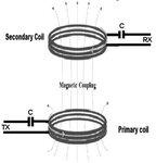
I created the RF template and choose wire option. Then, I created a substrate with the material FR-4(lossy). On the substrate, I created a rectangular copper and finally made a coil based on that. At the two ends of the coil, I added a capacitor to tune the circuit. In the outer of the coil, I created another coil to be power coil. Also, I added a discrete port at the power coil. Then, I copy this coil to make the other pair. When I start the simulation, the software told me that it will use a lot of time. So it cannot continue to get the final simulation result.
 

There are many ways to implement a WPT system. But was already proved in many publications and books that the series-series topology provides the best efficiency for power transfer.

https://ai2-s2-public.s3.amazonaws....b279a1bfc6b87f7dd53061ba4df6a/1-Figure1-1.png

Seems that you are using parallel-parallel topology, which has lower power transfer efficiency than series-series.

Anyway, whatever topology you use, to speed up the simulation time, very important is what profile you use for the cross-section of the wire.
Round wire cross-section it will take the longest simulation time, when square cross-section the shortest time. A good compromise between time and accuracy is to use hexagonal cross-section.
 
Capture.PNG

Hi, this is my design.

thank you. I post it below

WPT.PNG

This is the way I used to simulate the WPT.
 

As I suspected, you use parallel-parallel coupling.
If you use series-series, not only the power transfer efficiency will be better, but the circuit become simpler. And the simulation will be faster.
Use only two coupled inductor coils, one for TX and one for RX, each one having its own series capacitor to get the resonance. Do not use feed and load coils, that you have now.
Usually the secondary coil (for RX) has lower inductance than the TX coil (lower number of turns), to get higher loaded-Q with low impedance loads.
Check the net for WPT papers written by John T. Boys, and you get a lot of extra information on this topic.
 

Hi,

I draw a copper coil and add a capacitor to tune the circuit. When I simulated, I chose the Frequency Domain solver. But the result was not expected. My parameters are below:
L= 1.49uH C=92.4pF.
The cst file cannot be uploaded to the forum...Capture1.PNGCapture2.PNG

Thank you so much!!
 

I am a bit confused about your layout design.
Try to design only two inductor coils, one for TX and one for RX, placed one on the top of the other, for maximum mutual coupling (as in the picture attached).
You can make the inductors whatever shape you want, but hexagonal shape would be a good compromise between simulation speed and accuracy.
Capacitors C shall resonate with TX and RX inductors to the desired source (TX) frequency.
 

Attachments

  • wpt-coils.jpg
    wpt-coils.jpg
    19.2 KB · Views: 126

Thanks for your kind reply and suggestion! I will try it after I finish my design..
 

Status
Not open for further replies.

Part and Inventory Search

Welcome to EDABoard.com

Sponsor

Back
Top