Continue to Site

Welcome to EDAboard.com

Welcome to our site! EDAboard.com is an international Electronics Discussion Forum focused on EDA software, circuits, schematics, books, theory, papers, asic, pld, 8051, DSP, Network, RF, Analog Design, PCB, Service Manuals... and a whole lot more! To participate you need to register. Registration is free. Click here to register now.

74HC595 Shift Register Not Working

Status
Not open for further replies.

gauravkothari23

Advanced Member level 2
Joined
Mar 21, 2015
Messages
640
Helped
5
Reputation
10
Reaction score
4
Trophy points
1,298
Activity points
6,922
Hi all...
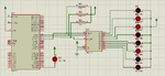
i am trying to interface 74HC595 Shift register with 89S52 (Circuit diagram attached).
it works perfectly in proteus. but when the same i try implementing in the actual hardware, nothing happens, the status on LED's does not change.
Can anybody please let me know where the problem is. i also tested the PCB for any shorts or broken tracks, but thats not a problem.
code:
Code:
#include <REG51.h>
#include <STDIO.h>

sbit data1 = P2^0;  //DS
sbit clock = P2^2;  //SH_CP
sbit latch = P2^1;  //ST_CP

sbit led = P3^7;

void msdelay(unsigned int value)
{
 unsigned int i,j;
 for(i=0;i<value;i++)
 for(j=0;j<100;j++);
}

void leddata(unsigned char databyte)
{
	int i;
	for(i=0;i<8;i++)
	{
		data1 = ((databyte&0x80) == 0x80);

		clock=1;
		msdelay(2);
		clock=0;
		msdelay(100);
		databyte = databyte << 1;
	}
	latch=1;
	msdelay(2);
	latch=0;
}

void main(void)
{
	data1=0;
	clock=0;
	latch=0;
	while(1)
	{
		led=~led;
		leddata(0xd9);
	}
}
 

Attachments

  • 74HC595.png
    74HC595.png
    85.4 KB · Views: 976

I didn't look that closely, but it looks like you're shifting at about 10 Hz. That seems pretty fast to mem.
 

it works perfectly in proteus. but when the same i try implementing in the actual hardware, nothing happens, the status on LED's does not change.
Aren't you aware that RESET pin should be pulled down to GND instead of tying to the VCC bus ?
Actually, it need an RC arrangement just to ensure proper timming for register's initialization.
 

Aren't you aware that RESET pin should be pulled down to GND instead of tying to the VCC bus ?
Actually, it need an RC arrangement just to ensure proper timming for register's initialization.

Actually my reset circuit is 10k resistor pulled down to GND with 10uF cap to VCC.

- - - Updated - - -

What changes do you recommend
 

Considering that the above schematic does not represent the actual assembly, just to check: Are you connecting a crystal or any oscillator to the microcontroller?

- - - Updated - - -

BTW: I would also consider tying EA pin to Vcc, just to avoid that the (not implausible) absense of any pull-up circuit to assert it to high logic level would force uC to fetch program instruction from external memory. You should confirm on datasheet whether it can be left unconnected or not; I'm obviously considering that you are making use of microcontroller's internal flash memory.
 

Not sure what you're expecting, but there's no shift action in the code, just LED pattern 0xd9 output repeatedly.
 

Not sure what you're expecting, but there's no shift action in the code, just LED pattern 0xd9 output repeatedly.

The shifting is the in the shift register, which shifts at 10 Hz, and will probably just look like one bright led and 7 dim ones.
 

Not sure what you're expecting, but there's no shift action in the code, just LED pattern 0xd9 output repeatedly.

yes.. i just need the LED pattern to be printed. but that's what not happening. but the same code working perfectly on proteus.

- - - Updated - - -

Have connected 11.0592 Crystal and EA pin to 5V to make controller read internal flash

- - - Updated - - -

The shifting is the in the shift register, which shifts at 10 Hz, and will probably just look like one bright led and 7 dim ones.

i have even tried giving delay of 2 seconds inside while, but still the LED pattern does not change

- - - Updated - - -

and i am sure that my controller is working properly because the single LED which is connected
Code:
sbit led P3^7
starts blinking as soon as i on the controller.
but when i write
Code:
void main(void)
{
        data1=0;
	clock=0;
	latch=0;
	while(1)
	{
		led=~led;
		leddata(0xff);
		msdelay(2000);
	}
}
the LED's in shift register does not go OFF.
 

Hi

and i am sure that my controller is working properly because the single LED which is connected
I'm not that sure...

Go back to proteus and show the signals on a proteus_scope. Let's see what they do...
But be sure to use the very same code as in the real circuit.

My recommendation:
Although proteus does not need power supply capacitors, an xtal circuit, current limiting resistors at the LEDs....I strongly recommend to draw all this into the schematic. This ensures that you don't miss to include them in the real circuit, and we see the correct circuit...

Klaus
 

O.K., you mean, the shift register doesn't work at all, LED output stays at all off or whatever the arbitrary initial state is.

Unlikely a coding problem, you'll check the hardware.
 

my reset circuit is 10k resistor pulled down to GND with 10uF cap to VCC
connected 11.0592 Crystal and EA pin to 5V to make controller read internal flash

Time to show a schematic that depict the actual circuit assembled; the one you sent initially is useless at all since at each new reply you add one more information diverging from the original circuit. Would have anything else not mentioned so far?
 

And one more thing: current limiting resistors for the leds? The most the '595 can sink is 6ma
 

Status
Not open for further replies.

Similar threads

Part and Inventory Search

Welcome to EDABoard.com

Sponsor

Back
Top