Continue to Site

Welcome to EDAboard.com

Welcome to our site! EDAboard.com is an international Electronics Discussion Forum focused on EDA software, circuits, schematics, books, theory, papers, asic, pld, 8051, DSP, Network, RF, Analog Design, PCB, Service Manuals... and a whole lot more! To participate you need to register. Registration is free. Click here to register now.

Can LM3914 be set up to work as an exclamation point and alarm flasher?

Status
Not open for further replies.
Hi,

Thanks for info. I still say that fitting two versions together may be more effort (and possibly parts) than makes sense to do virtually the same thing...

It seems there's no spice/simulation model for the LM3914 so out of curiosity I've been trying to make one that is adequate for simple simulation purposes to test theories.

So far I have a bar mode one working; thanks to KlausST's help I've been able to make the dot mode version. Fitting them together was a bit of a challenge and I had to pause the fun due to other commitments. I feel the provisional model is 2 steps from being usable but time is an issue for me right now. If I can find a minute on Sunday night I'll get back to the model so maybe Monday or later in the week we can see how the circuit I posted, and I have a more complete version of that now, too, fit together. I'd need to re-calculate some resistor values and so on.

I work and have other commitments so do not lead a life of leisure with endless free time, quite the opposite, so please bear that in mind...

Important to remember that first is idea converted to a design and then some maths, after simulation and/or breadboarding comes prototyping to correct (hopefully minor) discrepancies between simulation results and reality. This is a circuit you can make on a breadboard with PDIP parts and smooth out rough edges or flaws and quirks before making a soldered version.

Hope to get back to you soon!
 

Hi SparkyChem,

I wrote from the phone this morning so had to miss a few things out... I hate modern technology, especially Pepper the robot.

It's YOUR job to buy any parts you need and test the circuit or come up with another one and make it to test it, or commission someone to do ALL the work for you :). Surely you can show some interest and gumption and get hold of a breadboard and the basic components to experiment with at least the flasher one? Hobbies are about doing and learning, not expecting others to do, IMHO. What will you learn if someone else does everything else for you - how to ask someone to do what you should be trying to do??

By now, you should have pretty much memorised that datasheet from personal interest and a clear need to understand what you're hoping to do and come back with genuine questions, a set of calculations you have tried to do you may want checked for errors, ...and a proper schematic even perhaps.

I can't think of a better idea to make the exclamation mark version flash at a certain frequency than op ampos, comparators, inverters and an oscillator like the 555. That will be that I'm simplistic and can't see how to minimise the circuit, except for just doing the bar flasher one instead. The inverter IC after the comparator(s) is because the 555 reset pin needs to be low (0V) until the overvoltage event and then go high (V+) to make the 555 work.

The flasher version only needs a capacitor and resistor to do as it says under figure 20 on page 15 - flash when the RC junction is connected to any LED of your choice.

I have to say quite bluntly: One of my first circuits was an H-Bridge. I suffered a lot, A LOT, I knew next to nothing about electronics at all. I asked for almost no help, I suffered through rubbish schematics I found on the Internet, good schematics I didn't understand, typical beginner's mistakes of incorrectly wired BJTs and MOSFETs, burnt BC547s and BC557s, a burnt optocoupler, learning the wisdom of using fuses, what decoupling capacitors were, what a mechanical realy and a solid state relay could be used for, I did a lot of reading along the way to achieve MY goal, learn things, correct mistakes and beginner's naïve things like not knowing what pull-up and pull-down resistors were or were for. Felt like an idiot most of the time. It was fun and exciting, I applied myself to it and spent money and time to get the blasted thing to work. It was worth the effort. Around that time I made that LM3914 staple of the thermometer with 20 LEDs, it wasn't easy and took a few attempts to understand the schematic, online explanations and tiny bits of the datasheet - it was so exciting and fun to finally see the LEDs light up one by one on holding the LM35 temperature sensor on my breadboarded circuit. - What's your excuse precisely, fear, lack of funds or laziness or lack of real interest? I know it seems hard, but what isn't at first. We have nothing to fear but fear itself, and predatory governments and corporations, and maybe giant domestic cats the size of elephants if a mad scientist fond of felines abuses the Crispr thing...

And all that said, I will gladly help you, electronics is really hard at first and hideously confusing, Lord, do I know, but please make a bit more effort your side, it's your circuit, not mine.

Thanks for pointing out supply voltage. And on we continue. I'm hoping to continue with the simplistic LM3914 model tomorrow.

- - - Updated - - -
 

Hi SparkyChem,

I've been a busy bee today (besides all the hours on previous days for this ???labour of love??? to copy an IC)...

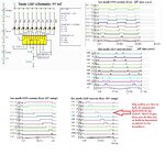
The model could be much better, it hasn't got the carry mode pin as I really do not feel inclined to spend a(nother) week getting that subcircuit to work. As you can see, the model performs the function of the LM3914 quite faithfully to say the least. It has been a lot of work for me, I have attached a copy of the actual circuit needed to copy this IC so you can that it is not just some quick thing to do... It's being fun, I must admit, but I won't be able to do any more on that level for a while.

I'll simulate the 555 with the crummy model I made tomorrow and let you know. I wonder if just using the RC version of the flasher with the exclamation mark version might work, that would be great - less parts; you'd still need to convert the -6V to +6V with an op amp, but that's life.

The spikes on the dot mode results are because the real LM3914 has hysterisis on the comparators to avoid that issue, my version doesn't and I have no intention of either doing the calculations or adding all those resistors now. I believe the model is more than fine to simulate a few things from what I can see, and believe you me - I have simulated this circuit so many times by now that my cat is beginning to not like me very much due to the time involved and I also look forward to saying goodbye to VG1 and VG2...

lm3914 copy LED schematic and results.jpg

lm3914 copy actual circuit.JPG

Get back to you in a few days or tomorrow, depending on what I have to do besides something I enjoy.

Have fun!
 

Hi again,

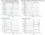
Have a version that goes from dot mode to bar mode for exclamation mark version at +6V or -6V input events. It doesn't flash (yet, not got that far and no time left today). It only needs - in addition to the two LM3914s and the LEDs - two diodes (preferably Schottky), two PNPs and two op amps (or half a quad op amp) and a negative voltage which can easily be created with the 7660 charge pump inverter IC (works from ~2 to 12V, ideal for 9V, and only needs two 10uF capacitors...).

lm3914 pos and neg response graphs.jpg

lm3914 6V pos neg dot to bar exclamation mark schematic.JPG
 

Status
Not open for further replies.

Part and Inventory Search

Welcome to EDABoard.com

Sponsor

Back
Top