Continue to Site

Welcome to EDAboard.com

Welcome to our site! EDAboard.com is an international Electronics Discussion Forum focused on EDA software, circuits, schematics, books, theory, papers, asic, pld, 8051, DSP, Network, RF, Analog Design, PCB, Service Manuals... and a whole lot more! To participate you need to register. Registration is free. Click here to register now.

PC817 circuit not working with relay

Status
Not open for further replies.

venkates2218

Full Member level 6
Joined
Sep 30, 2016
Messages
354
Helped
1
Reputation
2
Reaction score
1
Trophy points
1,298
Activity points
4,306
iMAGE_1.png

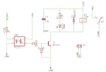
I'm trying to use PC817 in relay circuit.This is my circuit which I tired the PC817...
This circuit connected with an PIC16F877A controller for switching operation.I checked the controller output with LED which going to switch the relay.The LED is working fine,but the relay not switching ON,their is no response in relay....If the relay is directly ON by direct supply of +12VDC means working...
Is this circuit is correct or have to change in something..?
 

G2R 12V DC coil has 275 ohm nominal resistance, resulting in > 40 mA current. Please review PC817 datasheet for guaranteed output current. You surely need an additional transistor to boost the opto coupler current.
 

G2R 12V DC coil has 275 ohm nominal resistance, resulting in > 40 mA current. Please review PC817 datasheet for guaranteed output current. You surely need an additional transistor to boost the opto coupler current.

Image_2.png

Is this circuit is OK with values for resistor...
I'm going to make an flash light by using this circuit.The light will take nearly 2A,12VDC power.
If I switched the optocoupler frequently means,any damage will occur to optocoupler..?

Code:
while (1) {
flash_light= 1;
DelayMs(50);
flash_light = 0;
DelayMs(50);
}

this the code for flashing light.
 
Last edited by a moderator:

You must connect +5V to the collector of PC817 (pin 4), so swap pins 3 & 4.
Remove C4 or connect it to ground instead of T1 collector.
I would use a resistor between base and emitter for T1. You don't want a small leakage current in PC817 to partly switch T1 on. 1k to 10k is prabably OK.
 

You must connect +5V to the collector of PC817 (pin 4), so swap pins 3 & 4.
Remove C4 or connect it to ground instead of T1 collector.
I would use a resistor between base and emitter for T1. You don't want a small leakage current in PC817 to partly switch T1 on. 1k to 10k is prabably OK.

Image_3.png

Is this Ok..?
 

Optocoupler and transistor are connected correctly.

The schematic suggests you have same ground on both sides, which makes the opto coupler useless. You can drive the transistor by the µC port directly.
 

Hi,

It seems to be an EAGLE schematic.
How do you (wrongly) manage that there are no junction dots where the nets are connected? Usually EAGLE sets them automatically. This is a useful function.
Use the "Net" command to draw the nets.

Klaus
 
Optocoupler and transistor are connected correctly.

The schematic suggests you have same ground on both sides, which makes the opto coupler useless. You can drive the transistor by the µC port directly.

Relay and micro controller are powered by single power source only,the ground will be same for all over the circuit...That means their is no use of using optocoupler here..?
Is their any way to use optocoupler as effectively with same power source for both controller and relay circuit..?
 

while (1) {
flash_light= 1;
DelayMs(50);
flash_light = 0;
DelayMs(50);
}

You are trying to switch the relay in intervals of 50ms, which surelly is a time smaller than the one necessary to overcome the relay contact's mechanical inertia.

In addition, the BC547 were designed to handle maximum current of 100mA, whereas the above G2R relay is likely draining a current half of that, which sounds a small margin, considering that the relay needs a peak current on its comutation.
 

considering that the relay needs a peak current on its commutation.
Don't think so, 275 ohm coil resistance sets an absolute limit to the relays current. It also limits the transistor power dissipation in linear operation (e.g. due to insufficient base current) to 12²/(4*275) = 130 mW, so there's no risk to overload a BC547 (not considering wiring faults).
 
Neither the opto nor the relay makes sense to me in this application. Optos are for isolation. Relays are for isolation, ac current or high voltage/current applications. None of those apply.

A single power mosfet driven from the microcontroller directly can easily handle this application.

It needs to be a 'logic level' transistor and be suitably sized for low-rdson and power dissipation (SOT-89 seems about right to me on a first guess).
 

You are trying to switch the relay in intervals of 50ms, which surelly is a time smaller than the one necessary to overcome the relay contact's mechanical inertia.

In addition, the BC547 were designed to handle maximum current of 100mA, whereas the above G2R relay is likely draining a current half of that, which sounds a small margin, considering that the relay needs a peak current on its comutation.

shall we use CL100 instead of BC547..?
What's the required time to overcome relay contacts..?
 

It does sound like you may be better serveid with a PFET switch , rather than an opto and relay etc
A relay being switched on/off at 50ms also sounds suspicious......is there inrush?....if so, the relay contact bouncing with the inrush will damage the relay contacts if used for long periods with this 20Hz switching frequency.
 

Hi,

it´s already answered in post#6.

Klaus
 

Status
Not open for further replies.

Part and Inventory Search

Welcome to EDABoard.com

Sponsor

Back
Top