Continue to Site

Welcome to EDAboard.com

Welcome to our site! EDAboard.com is an international Electronics Discussion Forum focused on EDA software, circuits, schematics, books, theory, papers, asic, pld, 8051, DSP, Network, RF, Analog Design, PCB, Service Manuals... and a whole lot more! To participate you need to register. Registration is free. Click here to register now.

How to find if a frequency is being received by tuners ?

Status
Not open for further replies.

Externet

Advanced Member level 2
Joined
Jan 29, 2004
Messages
579
Helped
28
Reputation
58
Reaction score
29
Trophy points
1,308
Location
Mideast US
Activity points
5,664
Hi all.
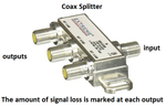
A coaxial cable carrying multiple signals on multiple frequencies, connected to a tuner.

Will the amplitude of the tuned signal decrease by the effect of tuning to it ?
If several tuners fed by the same coaxial are receiving only that same frequency, would that signal lose more amplitude than the others that are not being 'selected' by the tuner ?

Would a large number of tuners set to receive the same frequency result in detriment of that particular signal ?
 

Several tuners connected to a coax cable need a splitter so that their 50 ohms or 75 ohms inputs are not in parallel which would load down the coax cable signal. But of course the splitter will have a signal amplitude loss. Tuning or not tuning a signal has no effect on the signal amplitude in the cable. Here is a splitter:
 

Attachments

  • splitter.png
    splitter.png
    100 KB · Views: 62

Will the amplitude of the tuned signal decrease by the effect of tuning to it ?

Think this in terms of energy; yes, some signal is being used by the tuner that will cause a loading on the source.

In fact, the source can figure out that someone is listening! The loading on the source is minimal but cannot be zero because the tuner is far from ideal.

If the signal is at radio or TV frequency, you need to check the load (to reduce reflection) and match impedance (that shares energy optimally).
 

The answer depends on the tuner design. A tuner with a tuned input circuit before the first amplifier or mixer stage can be expected to have frequency depended input impedance respectively reflection factor. In this case, out-of-band signals may be partly reflected to the upstream. But state-of-the-art cable TV antenna jacks or splitters are designed as directional couplers, absorbing reflected signals. Thus possible reflections can't be seen by other cable network peers.
 

In fact, the source can figure out that someone is listening! The loading on the source is minimal but cannot be zero because the tuner is far from ideal.

The tuner will load the source wideband. The narrow band channel selection is further down the signal chain.
 

Right now my TV is tuned to a channel and might be loading down the cable a tiny amount. But it is not turned on!
Its input is 75 ohms at all frequencies when it is turned on or is turned off.
 

Thanks, gentlemen.
Being the source a probably near-to-zero output impedance, and the tuners load unknown; (because the 75Ω is a nominal label and unlikely that at a particular frequency) What would be a sensing method to find if a frequency is being tuned more than others ? Measuring current of each signal ?

Does plain TV-cable signals source compensates with AGC the weakened signal at the transmitting point due to losses by coaxial or tuning ?

How do dozens of TV channels are merged into single coaxial cable transmission; is it plain mixing or there is a obscure little-discussed method ?

Audioguru... There is no way the tuner presents 75Ω at all frequencies. Impedance is strictly tied and dependent on frequency. The connector used is 75Ω but the tuner impedance is all over the place. I will try to find a file that exposes such and will post later. Tuners manufacturers do not present input impedance specifications, off or on.

Not for tuners below, will keep searching that file...
 

Attachments

  • Z.png
    Z.png
    238.3 KB · Views: 72
Last edited:

Source and receiver impedances must be equal to avoid RF reflections in the cable. The graphs for antenna impedance does not apply for cable TV.
 

Being the source a probably near-to-zero output impedance
In other words, you have no clue of RF amplifier design, signal distribution and impedance matching.

There is no way the tuner presents 75Ω at all frequencies.
It's well possible, but not necessary. As explained before, even a mismatched tuner input will not cause problems due to the design of the distribution network. But like Volker and Audioguru, I would expect most modern cable tuners to have wideband 75 ohms matching. I wonder which device is shown in the post #10 impedance curves.

How do dozens of TV channels are merged into single coaxial cable transmission; is it plain mixing or there is a obscure little-discussed method ?
In case of analog cable TV it's combining of individual channel signals by linear couplers, not mixing.

Today's cable TV is however mostly digital with many channels modulated into a single carrier frequency. Demuxing of channels at the receiver is pure digital signal processing. As far as digital TV is concerned, the answer to the title question is simply "never".

With analog TV, the best chance to identify the received channel is to monitor spurious LO emissions.
 

Of course, nominal RF source impedance is 75 Ohm also.

There is no way the tuner presents 75Ω at all frequencies. Impedance is strictly tied and dependent on frequency. The connector used is 75Ω but the tuner impedance is all over the place.

It's better to keep the impedance near 75 Ohm. Otherwise if tuner input impedance is much different from cable impedance, due to multiple reflections your received power level will have a strong ripple across the band (cable length is many wavelengths).

And in any case, there is a lot of backward isolation (S12) between the wideband input stages and the actual channel selection in the IF. You will not notice a change in input impedance when another channel is selected.

As FvM mentioned, for known IF frequency the (small) LO leakage was a way to detect receive frequency.
 
Status
Not open for further replies.

Part and Inventory Search

Welcome to EDABoard.com

Sponsor

Back
Top