Continue to Site

Welcome to EDAboard.com

Welcome to our site! EDAboard.com is an international Electronics Discussion Forum focused on EDA software, circuits, schematics, books, theory, papers, asic, pld, 8051, DSP, Network, RF, Analog Design, PCB, Service Manuals... and a whole lot more! To participate you need to register. Registration is free. Click here to register now.

Supply LM741 with +5,-5 Volts

Status
Not open for further replies.

adwnis123

Full Member level 4
Joined
Jun 19, 2014
Messages
214
Helped
0
Reputation
0
Reaction score
1
Trophy points
18
Activity points
1,737
I am trying to built an amplifier with a Gain = 3. After many simulations with LM386 that didn't work, I conclude in using LM741. But it works well with only +5,-5 Volt supply. So, my question is how I can get +5 Volt and -5 Volt simultaneously from a single 12 Volt power supply, in order to supply the LM741?
 

Hi,

You may use a DC/DC converter with 12V input and +/-5V output.
This is a very simple solution.
But there are many other solutions...

May I ask:
* Why LM386 didn't work?
* why you don't you use the +12V? Why +5V?

Klaus
 
LM386 and LM741 are quite different devices and the 741 has very poor performance by todays standards.

What is the purpose of the amplifier and as Klaus asked, if you use a 741, why not run it from 12V rather than 5V.

Brian.
 
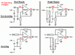
An opamp does not need a negative supply if you power it with a positive voltage and ground, then bias its (+) input at half the supply voltage like this:
 

Attachments

  • opamps.gif
    opamps.gif
    16.8 KB · Views: 240
... which I why I queried it's purpose. An LM386 cannot be externally biased to half rail but an LM741 can as described. It is also somewhat difficult to set the gain of an LM386 accurately to 3 and in any case whether they want power, current or voltage gain isn't quoted.

If the question related to two different op-amps it would be easier to understand but a choice of such different devices left me wondering what they aim to achieve.

Brian.
 
I have a signal 0,5Vpp - 1,5Vpp and I want to amplify it in order to do dsp with Arduino. I have made few simulations with LM386 with a single supply, but the amplified signal was not Ok. Then I used 2 supplies +V and -V, again wrong amplified signal. After many tests I concluded in 2 supplies and LM741

- - - Updated - - -

An opamp does not need a negative supply if you power it with a positive voltage and ground, then bias its (+) input at half the supply voltage like this:

Where I can find the values of the resistors?
 

Hi,

Reading your last post...
I don't think the problem is which amplifier to choose, which resistor value to choose or which power supply to choose.
To be honest: I think the problems are your electronic skills.

*****
Let's start from the beginning:
* you have an analog input signal
* and you want to feed it to the arduino's ADC (correct me if I'm wrong)

In the following there are a lot of questions...I know this sounds booring, but these are the requirements that tell you (us) which solution to choose. Best is if you can give values with units. Maybe you are not aware of all the answers, then at least try to explain in words.

Now let's define the input signal.
* the absolute input signal voltage range is: from -1.5V to +1.5V.
(if so, then you don't need to amplify the signal)
* what's the signal waveform: pure sine, squarewave, random like audio, please describe it.
* what's the source of the signal?
* what's the source_impedance of the signal?
* what's the signal frequency range?
* are you interested in the DC value of the input signal?
(If not then maybe you don't need an amplifier at all)

Arduino side:
Please tell us what you want to do with the signal?
What values do you want to measure and calculate?
What resolution, precision and accuracy do you want to achieve?
How often do you want to calculate the output values?
(Example: if you want to output your results on a display, then it's sufficient to calulate once per second up to 3 times oer second)

Solutions may be:
* just to re-wire your signal source (no additional part)
* just two resistors
* two resistors and a capacitor
* or an Opamp (difference) amplifier circuit (Opamp with 3, 4 or 5 resistors)
...all may be combined with filters

Klaus
 

I'm reading it slightly differently, the input signal is +0.5V to +1.5V and they want it scaling 0V - 3V.
That means subtracting 0.5V and a voltage gain of 3, presumably to best utilize the ADC resolution.

Firstly, the LM386 cannot do this, it is internally biased so it's output pin swings around half supply voltage and in any case it is designed for audio power applications where noise isn't too much of a problem. If you are using the ADC to best advantage you want the noise level to be as low as possible.

I would use a dual supply, simply because it makes a voltage subtraction easier. The actual supply rail voltages are not important as long as they are within the amplifier ratings, it is only the voltage at the output pin that matters. A dual supply saves you having to use rail-to-rail amplifiers and also simplifies the offset circuit. If you do use a dual supply, I strongly advise that you add a series resistor between the op-amp output and ADC input and wire a small Schottky diode (BAT54 for example) across the ADC input to limit any negative voltages you might inadvertently produce.

You can sum 0.5V and the signal you want at the op-amp input and use feedback resistors to set the gain to 3. If it makes it easier, you can use an inverting amp configuration and invert the ADC result in software after taking the measurement.

Brian.
 

Hi,

Reading your last post...
I don't think the problem is which amplifier to choose, which resistor value to choose or which power supply to choose.
To be honest: I think the problems are your electronic skills.

*****
Let's start from the beginning:
* you have an analog input signal
* and you want to feed it to the arduino's ADC (correct me if I'm wrong)

In the following there are a lot of questions...I know this sounds booring, but these are the requirements that tell you (us) which solution to choose. Best is if you can give values with units. Maybe you are not aware of all the answers, then at least try to explain in words.

Now let's define the input signal.
* the absolute input signal voltage range is: from -1.5V to +1.5V.
(if so, then you don't need to amplify the signal)
* what's the signal waveform: pure sine, squarewave, random like audio, please describe it.
* what's the source of the signal?
* what's the source_impedance of the signal?
* what's the signal frequency range?
* are you interested in the DC value of the input signal?
(If not then maybe you don't need an amplifier at all)

Arduino side:
Please tell us what you want to do with the signal?
What values do you want to measure and calculate?
What resolution, precision and accuracy do you want to achieve?
How often do you want to calculate the output values?
(Example: if you want to output your results on a display, then it's sufficient to calulate once per second up to 3 times oer second)

Solutions may be:
* just to re-wire your signal source (no additional part)
* just two resistors
* two resistors and a capacitor
* or an Opamp (difference) amplifier circuit (Opamp with 3, 4 or 5 resistors)
...all may be combined with filters

Klaus

*The source of the signal is sound from a mobile phone (through the audio jack)
*The signal frequency range is between 300 Hz - 6000 Hz (6 kHz)

*I want to supply the signal to an envelope detector, and from the envelope detector to connect it to the Arduino. As far as I have noise , Arduino will do nothing. When I have sound the Arduino will wait, and when the sound is gone the Arduino will switch ON a LED.
*I will use Arduino nano's ADC ---> 10 bit resolution
*I calculate the output values continuously

I want to amplify the signal because, it is difficult to know when I have noise and when I have sound, as it is the situation now...

Also, for the envelope detector what values do I choose for the Capacitor and the Resistor, concerning that the sound is 300 Hz - 6kHz?

- - - Updated - - -

The very simple opamp circuit uses resistor values calculated from knowledge of opamp spec's (input current) and other opamp circuits (experience).

That's why I am asking here, because I do not have the experience...
 
Last edited:

Is the level from the phone's headphones jack adjusted down to zero with its volume control?
Why does your phone produce lots of noise? There will be hum and other interference (from a light dimmer) if the output cable is not shielded.
 

Hi,

My thoughts.
Why the envelope detector in hardware? I find it more flexible and less prone to errors (drift, noise...) when you do this in software.

Input circuit.
The simplest solution could really be a series capacitor and two resistor to generate bias of Vref/2.
But 10 bits of ADC resolution isn't much for audio processing. Thus maybe an amplifer with relatively high gain, but with voltage limiter could be an idea to increase low signal detection, but not overdrive at high volume. I guess it's no problem when the high signal audio signal is distorted.

Additionally I recommend to use analog filters to focus on the frequency range of interest.

You say you calculate "continously"... you knoe you have a digital system...it is no continous.
If you want to calculate with every ADC sample.....I see problems. I really recommend to use a fixed ADC sample rate in any case...not runtime driven.
But what sample frequency? if you want to process up to 6000Hz then you need more than 12000Hz sampling rate.
But why try to calculate a result every 80us? Makes no sense to me.
I'd say one result per 100ms (this is more that 1000 times slower) should be sufficient.

******
But if you want to go with your envelope solution:
Use a filter, an limiting amplifier... but the use an evelope circuit that gives two values:
* either the DC (average) value and the envelope signal
* or two envelope signals: positive and negative.
With thus you can avoid that DC offset drifts can cause problems. It depends on the audio signal level you want to detect and the reaction time for detection.

Klaus
 

Hi,

My thoughts.
Why the envelope detector in hardware? I find it more flexible and less prone to errors (drift, noise...) when you do this in software.


Klaus


How to make that with software?Is it possible to feed the Arduino, with an audio signal that has positive and negative values?

I am using this circuit https://www.instructables.com/id/Tales-From-the-Chip-LM386-Audio-Amplifier/

but it has too high gain....

I only need a Gain =3, what changes should I do?
 

Hi,

Is it possible to feed the Arduino, with an audio signal that has positive and negative values?
Just add voltage at the analog side and subtract it on the digital side.
As said: C, R, R is sufficient. There are many threads dicussing this.

Klaus
 
Hi Brian,

a choice of such different devices

Not likely but beginners boxes come with such delights as a few of each of the following: 7805, 7812, 4001, 4013, 741, 386, 555.

Clearly, these learner kits are not all about offloading unsellable ancient parts noone with an iota of experience would purchase to novices who start the learning curve with prehistoric op amps and junk parts like the 741... But it does have offset null pins, making it really useful.
 
Hi Brian,


Not likely but beginners boxes come with such delights as a few of each of the following: 7805, 7812, 4001, 4013, 741, 386, 555.

Clearly, these learner kits are not all about offloading unsellable ancient parts noone with an iota of experience would purchase to novices who start the learning curve with prehistoric op amps and junk parts like the 741... But it does have offset null pins, making it really useful.

Ok, so I use two 7805 let's say, to get +5 Volt and -5 Volt from a single +12 Volt supply. Won't I have any problems such as short circuits...?

- - - Updated - - -

Since I use, a single supply from where I get 2 opposites supplies?
 

A 7805 makes +5V, not -5V. To make -5V then you need -12V to feed a 7905.

When you use a +5V and -5V dual polarity supply, you bias the (+) input of the opamp at 0V which is half the supply voltage. Then the input and output can swing up and down.
When you use a single polarity supply, you bias the (+) input of the opamp at half the supply voltage with two resistors. Then the input and output can swing up and down.

Most opamps do not need voltage regulators. They need a simple voltage with a normal filter capacitor.
I showed you in post #4.
 

Hi,

Also, besides not needing a negative supply as stated in above post, #17, the 78xx family have a hefty dropout voltage of around 3V. Nowadays there are far better devices like LDOs or other regulators that can provide both positive and negative outputs from one IC.
 

Status
Not open for further replies.

Part and Inventory Search

Welcome to EDABoard.com

Sponsor

Back
Top