Continue to Site

Welcome to EDAboard.com

Welcome to our site! EDAboard.com is an international Electronics Discussion Forum focused on EDA software, circuits, schematics, books, theory, papers, asic, pld, 8051, DSP, Network, RF, Analog Design, PCB, Service Manuals... and a whole lot more! To participate you need to register. Registration is free. Click here to register now.

Folded cascode biasing

Status
Not open for further replies.

usernamer

Newbie level 6
Joined
Oct 26, 2018
Messages
13
Helped
0
Reputation
0
Reaction score
0
Trophy points
1
Activity points
200
Hi all,
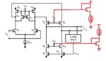
I have been looking for a book or something that explained how to bias a fully differential folded cascode OTA since in all books I have found so far, the cascode transistors' gate voltage is always set as a not better defined Vbias without explanation about how it is generated, is there some current mirror or similar?
Thanks to all those who will help
 

For NMOS cascodes use NMOS diode connected device to generate bias voltage with PMOS current source, for PMOS cascodes use the opposite.
This is a commonly used solution, very simple and practical, because the process variation will be the same for the cascodes and the diodes. They vary together with corners, but also important to use the same type of currents in the cascode and in the diode (for example both should get zero-TC current if you want to use zero-TC current in the folded-cascode amplifier). Thus the biasing can handle the temperature variation to.
 

Thank you for your reply, unfortunately I am a beginner (student) and not sure what you meant, do you mean I should make as shown in figure, I added the red parts?

If so, the Vgs of the diode connected device would be different from the Vgs of the device I want to bias, because its source is not at ground as it is the one of the diode connected device, should I use a cascode current mirror to get the wanted current on Q10 and Q6?

If not, I have not understood what you meant, could you please explain more in detail or link something for beginner where I could learn from?

Really grateful
 

Attachments

  • edaboard.jpg
    edaboard.jpg
    73.2 KB · Views: 283

There are many many techniques one of them simple like one I am attaching

You can find more advanced ones in CH5 in book Design of analog cmos IC by Behzad Razavi

I used M1 and M2 in biasing beause you need the current in this branch to be small and also you need M2 to be matched with Q5 and Q6.
So you need the size to be comparable to them ( or even number of multiples of M5 and M5 so that you can ensure to layout as common centroid)
The same concept applies to M3 and M4
M3 is matched to Q10 and Q8
M4 is used to make a VGS small and equal to VGS of M3 and M4

NOTE: that M4 and M2 can be replaced by resistors but in case of small currents (say 10nA or 100nA ) their size will be very large.

The ideal current sources is simply mirrored from one pure very good reference current and then mirror that reference currents to other circuits.

Untitled.png
 

The red parts on your figure are correct, and take a look at the circuit below please.

nnVBp9Um.png


In this circuit the Vgs.3 is else than Vgs.6,7. But it doesn't matter, because the point is that Vgs2=Vgs4=Vgs5, and Vds2=Vds4=Vds5 by the M1,M6,M7, so you can see now every voltages are the same around the M2,M4,M5 transistors.
Ids is Vgs and Vds dependent, thus Ids2=m*Ids4=m*Ids5, where m is the multiplier of M4,5.

I don't know how you imagine the cascode current mirror and where, but solution above should explain why not important to use stacked diodes to bias the cascodes. By the way stacked diodes are good because they also move together with the cascodes with process and temperature variations, but they decrease the output headroom of the cascodes, this why I prefer the biasing above, called low-voltage cascodes.
 
Last edited:

The point is that I do not think I can use wide swing current mirror you are showing because as you can see from the image I have attached, the Vgs of the bottom nmos should be provided by the common mode feedback circuit, so I cannot use the M1 and M2 transistors of your figure to get proper Vgs and Vds around Q7 and Q9 (or M4 and M5 in your figure) and thus neither the wanted current.
Am I right or missing something?
 

M4 is used to make a VGS small and equal to VGS of M3 and M4
View attachment 149738

Do you mean that M4 should make a Vds of Q7/Q9? If it is not so how can I make sure to mirror the same current through Q8/Q10?
And if so how can I achieve that? I do not see how to relate Vds of Q7 and Q9 to Vds of M4
 

The point is that I do not think I can use wide swing current mirror you are showing because as you can see from the image I have attached, the Vgs of the bottom nmos should be provided by the common mode feedback circuit, so I cannot use the M1 and M2 transistors of your figure to get proper Vgs and Vds around Q7 and Q9 (or M4 and M5 in your figure) and thus neither the wanted current.
Am I right or missing something?

You are missing that you set the current for the fully differential OTA at the top. The top PMOS transistors (Q3,4) set the required current values for Q7 and Q9, you can use low-voltage cascodes there. I wanted to highlight in the last comment that at the top cascode transistors for example this is not a requirement that Vgs of cascode has to be equal with an other biasing device's Vgs.
The common mode feedback (CMFB) circuitry will set Vgs for Q7 and Q9 to get the desired output common mode voltage, so NMOS cascode gate voltage doesn't matter. The CMFB doesn't set the quescient current of the branches, just tune the NMOS Vgs for the common mode. If you increase the cascode voltage, the Vds of Q7 and Q9 also increase, but the CMFB reacts to this, controls the Vgs down so current won't change.
 

Do you mean that M4 should make a Vds of Q7/Q9? If it is not so how can I make sure to mirror the same current through Q8/Q10?
And if so how can I achieve that? I do not see how to relate Vds of Q7 and Q9 to Vds of M4

Sorry for my late reply
Here you go
For M3 branch and Q8/10 branch say that the biasing current in M3 is 1/4 I8 or I10
then I3 = constant (w3/L) (VGS3-VTH)2
I8= constant (W8/L)(VGS8 - VTH)2
if you are going to desing it such that equal W/L for M3 and Q8/10 then
the VGS8= 2 (VGS3 -VTH)+VTH

Same method you will try if for example IM4 = 0.1 I8/10
Knowing that
VB3 = VGS8 +VDS7 = VGS3 + VDS4
So if VGS8 not equal VGS3
Than VDS7 not equal VDS4

On the other side
if you want to desing such that euqal voltages Then
I3 = constant (w3/L) (VGS3-VTH)2
I8= constant (W8/L)(VGS8 - VTH)2

Say again I want I3 = 0.25 I8
and make VGS 3 = VGS 8 (and so VDS7 will be equal to VDS4)
then
I3 = constant W3/L
I8= constant W8/L
4*W3/L = W8/L
(NOTE: L length should be the same for matching in the current mirror and you will have constraints to try to make the number of multiplers/fingers of W/L an even number for matching))
So then Voltages are the same but different W/L sizes
 

Status
Not open for further replies.

Part and Inventory Search

Welcome to EDABoard.com

Sponsor

Back
Top