Continue to Site

Welcome to EDAboard.com

Welcome to our site! EDAboard.com is an international Electronics Discussion Forum focused on EDA software, circuits, schematics, books, theory, papers, asic, pld, 8051, DSP, Network, RF, Analog Design, PCB, Service Manuals... and a whole lot more! To participate you need to register. Registration is free. Click here to register now.

Need Help Converting 150,000hz 3.3V 19.38mA DC Square Wave into 20Volt .2A A.C

Status
Not open for further replies.

z7d8tsg

Newbie level 6
Joined
Oct 26, 2018
Messages
11
Helped
0
Reputation
0
Reaction score
0
Trophy points
1
Activity points
84
Hi Everyone, Dan Here.

I Need Help Converting 150,000hz 3.3V 19.38mA DC Square Wave into 20Volt .2A A.C Square Wave Same Frequency.

Anyone have any ideas?

Thanks
-Dan
 

Yes, forget it!
3.3V at 19.38 = 0.0639W
20V at 200mA = 4.0W

It is impossible to create power, only convert it from one kind to another, you are asking for 3.936W to appear out of nowhere.

Brian.
 

I am trying to Amplify not Convert

I have an old laptop Charger to power everything: It is DC 32V 720mA LPS
It just needs to be run through a Voltage Doubler Circuit and then refined.

Thanks
-Dan
 

Hi,

What about a half bridge?

There are integrated circuits.

Klaus
 

Hi,

What about a half bridge?

There are integrated circuits.

Klaus


Klaus, Let me know what IC's that you are talking about. I am interested. Thanks

- Dan
 

Hi,

Did you do a search at your electronics distributor?
Half bridge, full bridge, H bridge, motor driver.....there are many names.

Klaus
 

Your incoming signal is 3.3V pulsed DC. It can drive a half-bridge although you need three transistors to provide necessary bias on/off.

Your power supply is 32VDC. You wish to derive split +-20VAC.

You can charge 2 series capacitors (one after the other) which gives you the voltage doubler effect. By placing an inductor in a strategic location you can create a buck converter effect, giving you +-20V. This wastes less power and runs cooler.

(Or else drop extra 12V via resistive drop in resistors transistors. However this method wastes several watts.)

Or, you can construct a charge pump converter which derives a negative supply in addition to your positive. Then you have +20 & -20 V.
 

Hi,

There are ready to buy DCDC powr supplies with +/-24V output.
24V x 0.2A = 4.8W
This means about 10W in total.

You may use linear regulators to drop down to 20V, each linear regulator will dissipate (24V - 20V) × 0.2A = 0.8W.
A small heatsink will do.

Klaus
 

Klaus, I already tried a Half Bridge and Full Bridge Rectifier, but the 3mhz N channel mosfets I bought, were not fast enough for some reason. All the I.C's that I've found for the 150khz range, top out at .1 Amperes Output for some reason - I don't want to use 2 of those IC's because of efficiency. Can anyone advise me on some mosfets or I'C's that may work here?

Brad, I am noob to electronic circuits. Can you post a picture of circuit? I thought you could only double voltage using A.C input using capacitors. The whole point of this project is so that I don't have to use anything that is plugged into a wall outlet socket.

Thanks
 

I found this circuit, but still haven't tried it yet. Anyone know of any more efficient or better alternatives?

Thanks ivGHT.png

- - - Updated - - -

Anyone have any recommendations for an (IGBT Driver and IGBT Combo) or (Mosfet Driver and Mosfet Combo) that could do this? I cannot find an ideal combo...

I am inputting 150khz 3.3V 19.38mA D.C Square Wave in order to ouput 150khz 20V P2k .2A A.C Square Wave

Thanks
 

I am inputting 150khz 3.3V 19.38mA D.C Square Wave in order to ouput 150khz 20V P2k .2A A.C Square Wave
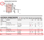
The specification is still ambiguous. What's the meaning of 19 mA? Maximum current tolerated by the source or 170 ohm output impedance? What's 20V, peak to peak or simple peak (= 40V pk-pk)? Any rise/fall-time requirements? What kind of load is driven by the driver?

A discrete push-pull driver as shown in the latest post seems appropriate. "more efficient or better alternatives" - depends on your exact requirements, see above. If it's 20V pk-pk, it can be well achieved by a high voltage gate driver IC. There are a few IC solutions suitable for 40V pk-pk, but discrete design is probably better.
 

Hi,

...
I assume (but only by the given circuit) the task is to form a 0V/3.3V square wave to a +20V/-20V square wave.
The given circuit's output voltage is GND referenced.

Another aproach is using a full bridge, where the output voltage is measured between the two output pins.
The benefit is that you don't need a negative supply. A singke +20V is used to generate +/-20V output.

Klaus
 

View attachment 149740

I am inputting 150khz 3.3V 19.38mA D.C Square Wave in order to ouput 150khz 20V P2k .2A A.C Square Wave

Your schematic can be the start of constructing a full H-bridge (as suggested per post #12).

H-bri 4 transis mixed NPN PNP 32VDC 150kHz to 25VAC sq wa to load.png

The incoming 3.3 VDC pulses are sufficient to bias an NPN transistor. This controls a half-bridge (notice it has N-device at top).

Its middle node has voltage changes which are able to provide bias for the opposite half-bridge (notice it has P-device at top).

The load gets greater than 20 V. This can be solved if we increase resistive drop in several components. However that is not the most efficient method.
 

Hi Brad, Thanks for the post. I will try it out.

Does anyone just want to build an extremely efficient model of this or send me a circuit diagram, in exchange for money?
please email me with interest:

Thanks

-Dan

- - - Updated - - -

This is the other Circuit that I Found Other Solution.png
 

Attachments

  • TO Post.png
    TO Post.png
    140.3 KB · Views: 157

Below is a circuit for Driving a H bridge with 2 Optocouplers.
I haven't tried it yet, but I see no reason why it cannot work.

Other Solution.png

This following link is of a LTC444# circuit I got from my post at eevblog - that apparently could work too: https://www.eevblog.com/forum/rf-mi...0volt-2a-a-c-s/?action=dlattach;attach=558955

Apparently, there are also many Full Bridge Mosfet Driver Chips Out there on the market, that can be easily fashioned for this. I'm not sure, I don't have tested and documented proof of this yet.

Anyways,
Which circuit do you guys think is best for efficiency?
thanks
 

Status
Not open for further replies.

Similar threads

Part and Inventory Search

Welcome to EDABoard.com

Sponsor

Back
Top