Continue to Site

Welcome to EDAboard.com

Welcome to our site! EDAboard.com is an international Electronics Discussion Forum focused on EDA software, circuits, schematics, books, theory, papers, asic, pld, 8051, DSP, Network, RF, Analog Design, PCB, Service Manuals... and a whole lot more! To participate you need to register. Registration is free. Click here to register now.

3 PH Power Factor Meter Designing Related

Status
Not open for further replies.

baileychic

Advanced Member level 3
Joined
Aug 2, 2017
Messages
728
Helped
56
Reputation
112
Reaction score
57
Trophy points
28
Activity points
7,033
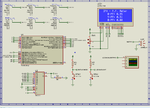
My question is 3 PH Power Factor Meter Designing Related. I am using PIC18F26K22 and have completed the coding part. I want to know how I can design the ZCD interface circuit. I am designing the Power factor meter for a client. Client is using 3x 100:5 C.T.

Load will be a 3 PH motor which draws max 15 Amps.

So, C.T. secondary current for 15 Amps input will be 750mA.

I am planning to use simple one resistor and two 1N4148 or 1N4007 diodes for the ZCD circuit. The upper diode cathode is connected to +5.0V and lower diode anode is connected to GND.

To get say 10V from C.T. output I have to use 13.34R or approx 15R but problem is power dissipation in resistor.

Pr = 0.75 * 0.75 *15 = 8.4W.

So, should I use capacitor and resistor in series for the burden so that there will be some reactance and not much power is dissipated in burden resistor ?

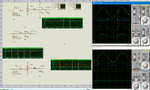
Find the attached Proteus simulation of the project.

I am using 1x 440V to 9-0-9V 1A transformer to get 5V power supply and R-V-ZC. I am using 2x 440V to 9V 250mA transformer to get Y-V-ZC and B-V-ZC signals.

Problem is with burdern resistor value.
 

Attachments

  • 3 PH Power Factor Meter.rar
    46.7 KB · Views: 74
  • Simulation WOB.png
    Simulation WOB.png
    77.4 KB · Views: 107
Last edited:

Hi,

PF measurement vs phase angle.
Mind that power factor and phase angle are not the same. You may convert one into the other only if you have clean sinusoidal voltage and current signals.

ZCD: I´d use a comparator. Inverting input to GND, non inverting input to input signal.
The circuit depends on your specifications:
* input voltage range
* desired output signal
* timing
* accuracy...

To get say 10V from C.T. output I have to use 13.34R or approx 15R but problem is power dissipation in resistor.
Why do you want 10V? you need to check if your CT is able to produce 10V without going into saturation.
Use a smaller burden resistor value to get less power dissipation.

Capacitor and resistor in series --> this will kill your phase alignment and thus it will destroy the measurement result.

Y-V-ZC:
You need careful selection of transformer and it´s load circuit to get accurate phase information.

****
Do a forum search, there a lot of PF measurement discussions.


Klaus
 

Thanks KlausST.

These are the three ZCD circuits that I have designed for x-V-ZC. For z-I-ZC I am thinking about using burden resistor, current limiting resistor and two 1N4148 diodes.

What value resistor can I use without worrying about power dissipation in resistor. I can max use 2W resistor for burden.
 

Attachments

  • ZCD Circuits.png
    ZCD Circuits.png
    195.1 KB · Views: 92

Hi,

I can max use 2W resistor for burden.
You know:
* I = 750mA
* P = 2W
* P = V x I
--> you are able to calculate V

Then you have V and I.
--> then use Ohm´s law to calculate R

Klaus

- - - Updated - - -

Hi,

your circuits:
* if you want digital output, then use a comparator.

***
* your input is AC. This means positive as well as negative. With negative input voltage you usually need negatve supply voltage for the comparator.
--> see datasheet "input voltage range"

What is your desired output signal vs input signal. Show us a drawing. With voltage and timing informations.

Klaus
 

Okay. I will calculate.

V required is 4.7V. 3 PH voltage varies between 400V and 480V and hence motor current also varies slightly.

2W resistor cannot be used to dissipate max 2W continuously ?

4.7V/0.75A = 6.2R

We can choode 6.8R

Pr = 0.75 * 0.75 * 6.8 = 3.825W.

So, should I use 5W resistors for burden resistors ? Does 5W resistors come in 6.8R ?

My desired output signal must be a square wave (ZC signal). My input signal is a sine wave.
 

Do I understand right that the circuit's purpose is to measure only phase angle(s) between current and oltage, but no current and voltage magnitudes? How do you deal with asymmetric currents involving different phase angles?
 

Yes, device is only for measuring phase angles and then power factor. Voltage and current magnitudes are not measured. P.T. and C.T. are used. 3x qty each. What do you mean by asymmetric currents ? Harmonics ?

If yes, I will put a low pass filter which rejects all freuencies above 65 Hz. Mains freuency is 50 Hz and 3db cut of freuency will be 65 Hz.
 

Yes, device is only for measuring phase angles and then power factor. Voltage and current magnitudes are not measured. P.T. and C.T. are used. 3x qty each.

From the graphs you can see that the ZC pulses are not correctly aligned; they are alternately aligned to the leading and trailing edges.

If you assume that the waveforms are sinusoidal and approx equally loaded (they are fed from the distribution transformer with large reserve capacity), then the six pulses (three each from potential and current lines) are sufficient to calculate the phase angle and power factor.

With this, you should be able to update the power factor every 10 cycles (even 5 cycles) without problem.

On the other hand, if the waveform is not sinusoidal (say harmonic content is more than 10%), then this approach will not work; you need to sample at least 20-30 samples per cycle (perhaps more; depends on the distortion) and integrate numerically. I would consider this approach much more robust in principle.
 

@ c_mitra

Why can't be harmonics bypassed using low pass filter ? Harmonics will have higher frequency than fundamental frequency.
 

Why can't be harmonics bypassed using low pass filter ? Harmonics will have higher frequency than fundamental frequency.

Of course you can bypass the harmonics. The question that will be asked: is the power factor same with OR without harmonics?

Wikipedia has an article on power factor: the talk page makes interesting reading!

If the load is not symmetrical (balanced), wikipedia says that the power factor is not defined. For symmetrical loads, the power factor is the same for all the three phases.

I was under the impression that there will be three numbers (three power factors) each one for each phase.

Note that RMS voltages and currents are always defined.
 

@FvM

By asymmetric currents do you mean non-sinusoidal currents ?
 

With asymmetric, I mean different current magnitudes and phase angles in 3 PH lines. No problem if you have only 3 phase motor load, but can easily happen with mixed load. Calculating individual power factor numbers for three phases would solve the problem, but is somehow unusual.

Of course you can bypass the harmonics. The question that will be asked: is the power factor same with OR without harmonics?
Generally not. Power factor is ratio P.F. = P/√(P²+Q²+D²), with P = real power, Q = reactive power, D = deformed (harmonic) power. If you filter out fundamental voltage and current, you see only real and reactive power. Harmonic components present in the ZCD input can cause measurement error with the discussed zero crossing method.
 

Hi

in addition to FvM´s post:

With the equation given by FvM you now should see the difference between phase shift (and cos(phi)) vs power factor.

is the power factor same with OR without harmonics?
To supress the harminics you need a low pass filter. A first order filter won´t do the job, thus you need a higher order filter.
But every filter introduces phase shift. It will introduce phase shift to the fundamental frequency.
and .. oops .. this is the value you want to measure. I see problems.

Klaus
 

The "real" power is simple:∫v(t)•i(t) dt taken over one complete cycle (if the period is T, you need to divide the integral by T to get power).

This formula (i.e., (1/T)*∫v(t)•i(t) dt) always gives the power irrespective of the waveform.

But I do not know what is the defining terms for "other powers"

But it can get messy. For example, if you have a square wave (instead of a sine wave), life gets miserable.
 

I will filter out the harmonics using low pass filters for 3x V ZC channel and 3x I ZC channels. I have a new idea. Can I do like this ?

That is,

I use one 100:5 C.T. to get 0.75 Amps from 15A motor current (15 * 0.05). Then if I use another C.T. of 100:5 connected to secondary of 1st C.T. then I get 0.75 * 0.05 = 0.0375 Amp and 0.0375 * 200 = 7.5V. So, 200R will be the burden resistor.

Then

Pr = I^2 * R = 0.0375^2 * 200 = 0.2812W and so I can use 0.5W resistor for burden.

Will this work ?
 

Sounds like waste of resources. Why not use a low ohmic shunt followed by an amplifier? You want electronic filters, so you'll most likely have OPs anyway. Also consider that you have decided to ignore current magnitude information, respectively no need for exact scaling.
 

Hi,

I personally find your post somehow confusing.
There are a lot of open questions.
One time we asked why you want 10V. No answer, but now you try to achieve 7.5V.
7.5V RMS means about 20Vpp on a pure sinewave. (It might be more or less with your application).

Filtering overtones ... gives a better PF to phase angle relation for the filtered signal, but not for the original signal.
Are you aware that phase angle, or better say cos(phi) is different to power factor for non sinusoidal (original) signals?

Even if you have a 7.5V signal and you are satisfied with this ... you need some circuit to form a digital signal from it.
Usually a comparator.
But for a comparator it's more comfortable to work with lower voltages than with 20Vpp.
Are you aware that usually you need a power supply for the comparator that is wider than the input signal? At least +12V and -12V?
Then you need additional circuitry to generate logic level signals from the comparator output signal.

Two CTs in series:
I'm not sure if a CT is able to generate 7.5V output voltage from 37mA input current. There are limits, you need to read it's datasheet.

I see a lot of random ideas ... but less elaboration.

Example:
You want to measure timing of a zero cross.
Do you think timing of zero cross of a 750mV signal differs from the timing of the same waveform with 7.5V?
So why do you insist on the high voltage? That brings power dissipation problems, power supply problems and maybe CT linearity problems?

Klaus
 

My humble opinion: phase is defined in respect of a sinusoidal wave; if you have lots of harmonics, you cannot define phase.

What is actually meaningful is this: you do a spectrum analysis of the source and each sine wave component will have its associated phase.

If I understand correctly (what I have been taught and what I have learnt) that any filter (it does not matter whether it is passive or active) will affect the phase because it is going to remove the Fourier components from the results.

What is meaningful is that phase measurement needs a reference: you use the voltage source as the reference and use the current source to compare: (simply the zero crossings of the two signals with respect to the period taken as 360)- this assumes the sinusoidal nature of the both signals.

For a balanced load (e.g., a three phase motor) all the three phases are equal. But if the three phases are connected to different loads (unbalanced load), then there will be three phase values corresponding to the three lines and getting anything more than that is theoretically meaningless.

Once you decide on a flow chart or a block diagram, the details can be worked out.

I will filter out the harmonics using low pass filters for 3x V ZC channel and 3x I ZC channels. I have a new idea. Can I do like this ?

Of course you can do whatever you want but the question will remain: the phases will get shifted by unpredictable amount.

My suggestion: measure the shift and compare it with the period and get the phase (if there are lots of harmonics the result will not have any theoretical significance) but will only be a guide.
 

Of course you can do whatever you want but the question will remain: the phases will get shifted by unpredictable amount.
Why unpredictable? Using identical filters for voltage and current (with sufficient harmonic supression) will give the exact fundamental phase shift. If you want just this information, the method is straightforward.
 

Status
Not open for further replies.

Part and Inventory Search

Welcome to EDABoard.com

Sponsor

Back
Top