Continue to Site

Welcome to EDAboard.com

Welcome to our site! EDAboard.com is an international Electronics Discussion Forum focused on EDA software, circuits, schematics, books, theory, papers, asic, pld, 8051, DSP, Network, RF, Analog Design, PCB, Service Manuals... and a whole lot more! To participate you need to register. Registration is free. Click here to register now.

Transfer data's of seven segment

Status
Not open for further replies.

gauravkothari23

Advanced Member level 2
Joined
Mar 21, 2015
Messages
640
Helped
5
Reputation
10
Reaction score
4
Trophy points
1,298
Activity points
6,922
Hi all..
I have to make a project where i need to transfer the data's of seven segment display to other board using 89S52.
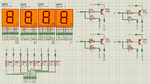
I have one board where 4 seven segment display has been interfaced to port 0 of 89S52 (MAIN BOARD) using 10K External pull up resistor. i dont have the source code of this controller so cant make any changes to it. but what i have to do is, whatever things are been displayed on this seven segment have to display in again on other seven segment display located at approx 1 to 1.5 metres away.
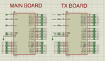
so now what i have done is, i have made two new boards one is TX board and other is RX board. the controller of TX board in connected to controller of MAIN BOARD with same pin No.
Ex.
P0 of Main board to P0 on TX BOARD
P1 of Main board to P1 on TX BOARD
P2 of Main board to P2 on TX BOARD
P3 of Main board to P3 on TX BOARD

so now whatever happen in MAIN BOARD, i can keep a track on it using my TX BOARD. so again now using serial communication i need to transfer the data's from TX BOARD to RX board where again seven segment display is interfaced.
when i power the system, the MAIN BOARD displays 1234 on 7 segment for 5 seconds and then it prints EROR continuously, which i need to transfer it to RX BOARD using TX BOARD.
Code for TX BOARD:
Code:
void UART_Init(int baudrate)
{ 
    SCON = 0x50;  // Asynchronous mode, 8-bit data and 1-stop bit
    TMOD = 0x20;  //Timer1 in Mode2.
    TH1 = 256 - (11059200UL)/(long)(32*12*baudrate); // Load timer value for baudrate generation
    TR1 = 1;      //Turn ON the timer for Baud rate generation
}

void UART_TxChar(int ch)
{
    SBUF = ch;      // Load the data to be transmitted
    while(TI==0);   // Wait till the data is trasmitted
    TI = 0;         //Clear the Tx flag for next cycle.
}

void main()
{
	while(1)
	{
		UART_Init(9600);
		UART_TxChar(P0);
	}
}

Code for RX Board
Code:
void UART_Init(int baudrate)
{ 
    SCON = 0x50;  // Asynchronous mode, 8-bit data and 1-stop bit
    TMOD = 0x20;  //Timer1 in Mode2.
    TH1 = 256 - (11059200UL)/(long)(32*12*baudrate); // Load timer value for baudrate generation
    TR1 = 1;      //Turn ON the timer for Baud rate generation
}

char UART_RxChar(void)
{
    while(RI==0);     // Wait till the data is received
    RI=0;             // Clear Receive Interrupt Flag for next cycle
    return(SBUF);     // return the received char
}

void main()
{
	segment1=0;
	segment2=0;
	segment3=0;
	segment4=0;
	while(1)
	{
		UART_Init(9600);       //Initialize the UART module with 9600 baud rate		
	  P0 = UART_RxChar(); // Receive a char from serial port
	}

but there is a bit problem with transfer of data's, because if the display on main board shows "1234", the RX BOARD only display "1" continuously on all 4 segment and after some time when MAIN BOARD display "EROR", the RX BOARD only display "E" all 4 segment.
i agree that switching of seven segment display is quite necessary, as i am not expecting to print 1234 at the time, but at least it should print 1 2 3 4 or EROR repeatedly, which agreed wont even be readable, as i am not doing any switching.
is there any error with my code.
 

You need to expand it slightly, at the moment you are transferring the segments as a single byte, that works fine for one digit as you have seen. You need to send another 4 bits (2 if you encode them) to say which of the digits is being sent. So as well as the segment information you can tell it which of the digits the segments are from. The easiest way is to encode the segments into a four bit number (in software) and to encode the digit position in the other four bits, so you still only send 8 bits but it contains all the information instead of just one number.

Like this:
your 8 bits sent through the UART are: DDDDSSSS
where DDDD is the position of the digit in the display and SSSS is the number on that digit.

You also probably don't want to Init the UART for every byte, it should only need doing once.

Brian.

ok.. got it...
i think your process and concept is quite good and easy to interface. will definitely try using it..
but just for an information i need to know what is the error which my initial code that its not working properly.
 

I think your original error is because there is no way to tell which digit is being sent, there is no sync between the two ends. I assume you have the segments connected to P0, what happens is the value on P0 is sent by the UART whenever it is ready to send more data. The value on P0 depends on which digit is active at the time but the UART doesn't know which it is.

Think of the UART data as being a conveyor belt between the TX and RX devices, at the TX end more is put on the belt as soon as there is a gap and at the RX end it is taken off at fixed intervals. The order of items on the conveyor cannot be guaranteed when the loading and unloading are at different rates.

Brian.

Thanks..
but right now i am not concentrating on, which segment value is being sent, right now i only want to know if all the values of P0 is being sent or not.
for example, initially MAIN BOARD segment prints "1234". so initially i dont need to print 1234 in my RX BOARD, first i need to check if all the four digits("1234") are being properly sent or not. and that is the error what i am getting.
the MAIN BOARD print "1234", but at the same time the RX BOARD should also print "1111" and then "2222" and then "3333" and then "4444". i agree that this values wont be readable at RX board because it might change at a rapid speed. but that's what not happing. the RX board only print "1111" continuously.

- - - Updated - - -

when the MAIN BOARD print "1234", i am only getting "1111" and missing out the other values in my next loop.
so i think the controller connected to MAIN BOARD is not able to scan the P0 of MAIN BOARD, as it might be busy in sending data's serielly, please correct me if i am wrong. so in such cases do i need to increase the value of crystal, so the controller for scanning the MAIN BOARD will run faster than it, and might able to scan the ports
 

A faster crystal probably wont help.
The most likely problem is the way you initialize the UART. Normally the bit rate (Baud rate) is generated by it's own timer and stays running continuously when initialized. Your code resets it after every character is sent or received.

Check the data sheet on how to program the Baud rate and do it once at the start of your program, you don't need to do it again in the loop.

Brian.
yes i have changed my code, now i am initializing it only at the time of startup. but then too the same problem arises.
 

Please show your new code so we can see it's current version.
A schematic of your connection to the segments would also help.

Brian.
 

Please show your new code so we can see it's current version.
A schematic of your connection to the segments would also help.

Brian.
here's my new code for both RX and TX Board
Code for TX BOARD:
Code:
void UART_Init(int baudrate)
{ 
    SCON = 0x50;  // Asynchronous mode, 8-bit data and 1-stop bit
    TMOD = 0x20;  //Timer1 in Mode2.
    TH1 = 0xFD;
    TR1 = 1;      //Turn ON the timer for Baud rate generation
}

void UART_TxChar(int ch)
{
    SBUF = ch;      // Load the data to be transmitted
    while(TI==0);   // Wait till the data is trasmitted
    TI = 0;         //Clear the Tx flag for next cycle.
}

void main()
{
        char seg;
        UART_Init(9600);
	while(1)
	{
                seg=P0;
		UART_TxChar(seg);
	}
}
Code for RX Board
Code:
void UART_Init(int baudrate)
{ 
    SCON = 0x50;  // Asynchronous mode, 8-bit data and 1-stop bit
    TMOD = 0x20;  //Timer1 in Mode2.
    TH1 = 0xFD;
    TR1 = 1;      //Turn ON the timer for Baud rate generation
}

char UART_RxChar(void)
{
    while(RI==0);     // Wait till the data is received
    RI=0;             // Clear Receive Interrupt Flag for next cycle
    return(SBUF);     // return the received char
}

void main()
{
        char seg;
	UART_Init(9600);       //Initialize the UART module with 9600 baud rate		
	segment1=0;
	segment2=0;
	segment3=0;
	segment4=0;
	while(1)
	{
	  seg = UART_RxChar(); // Receive a char from serial port
         P1=seg;
	}

- - - Updated - - -

Please show your new code so we can see it's current version.
A schematic of your connection to the segments would also help.

Brian.
This is the schematic of my RX Board

- - - Updated - - -

Please show your new code so we can see it's current version.
A schematic of your connection to the segments would also help.

Brian.

Thats my TX and MAIN board

- - - Updated - - -

sorry.. but i forgot to mention one thing, that the seven segment in the MAIN BOARD has been interfaced using SN74HC373. but the same in my RX board i have not used any IC's.
 

Attachments

  • Seven Segment RX.png
    Seven Segment RX.png
    107.9 KB · Views: 119
  • Seven Segment TX.png
    Seven Segment TX.png
    40.4 KB · Views: 131

Hi,

Naming of "SEG-A" ... "SEG-H" is correct
but to avoid confusion I´d rename "SEG-DISP-x" to "DIGIT-x" (x = 1, 2, 3, 4)

Your code is not complete. We don´t see how "segmentx" is related to a port pin. (and also other signals)

You set all "segment-x = 0". Are you aware that this means you enable all digits at the same time? You need to time multiplex the digits. --> Search for existing forum discussions.

You set "P1=seg;" but you don´t take care about different digits.

In TX-Board you set "seg=P0;" Are you aware that you don´t care about different digits?

I really wonder how you can think your code can work properly.

Am I right: You didn´t draw a timing chart for display signals nor did you draw flow chart for your code ..
--> This is urgent and every professional designer needs to do this, too. Please don´t expect that users here do this basic job for you.


Klaus
 

Hi,
Your code is not complete. We don´t see how "segmentx" is related to a port pin. (and also other signals)
Klaus
The schematic which shows 7 segment is RX BOARD and other schematic is of TX and MAIN BOARD. so the schematic i have sent wont relate to port pins of controller schematic i have sent, sorry for not attaching the RX board controller schematic.

Hi,
You set all "segment-x = 0". Are you aware that this means you enable all digits at the same time? You need to time multiplex the digits. --> Search for existing forum discussions.
Klaus
yes, i agree that i have set all the segment to '0', because as i told, its my initial test where i only need to know if all the data like "1234" are transmitted to RX board or not. switching the segment will do it once this part is resolved.

Hi,
You set "P1=seg;" but you don´t take care about different digits.
In TX-Board you set "seg=P0;" Are you aware that you don´t care about different digits?
I really wonder how you can think your code can work properly.
Klaus
sorry.. but did not get this point. different digits..??
P1=seg is inside the while loop. so every time it will scan the port 1 and send it to RX BOARD. so every time the digit changes from 1 to 2 or 2 to 3, the value of P1 also changes.
 

This takes us full circle. The code seems better now but as mentioned as far back as post #2, unless you also tell it which digit is being displayed it cannot possibly work properly. The output of the RX port could be any of the digits or even part of one digit and part of another.

What you need to do is read digit 1, send it, display it as digit 1.
read digit 2, send it, display as digit 2.
read digit 3, send it, display as digit 3.
read digit 4, send it, display as digit 4.

At the moment you read any digit, send it, display it. The 'any digit' could be 1, 2, 3 or 4 or none or a mix of two digits.

Brian.

i agree with you sir...
according to the code which i have written, the RX BOARD will display any digit, and it could be 1 ,2 , 3 , 4 or non or mix or anything. but that's what its not happening, it just displays "1" continuously without any flickering.
i mean to say that according to the code the RX board should display all the numbers and at a rapid speed, where again the things wont be readable. that's what its not happening. if the things happen then i can make it out that my code is working properly and then i can move further and make changes as you said:
read digit 1, send it, display it as digit 1.
read digit 2, send it, display as digit 2.
read digit 3, send it, display as digit 3.
read digit 4, send it, display as digit 4.
 

Hi,

The schematic which shows 7 segment is RX BOARD and other schematic is of TX and MAIN BOARD. so the schematic i have sent wont relate to port pins of controller schematic i have sent, sorry for not attaching the RX board controller schematic.
I´ve seen the schematic, but you need to include thie information into the code. Don´t show us code snippets. (currently we see a TX board snippet and a RX board snippet)

yes, i agree that i have set all the segment to '0', because as i told, its my initial test where i only need to know if all the data like "1234" are transmitted to RX board or not. switching the segment will do it once this part is resolved.
It´s impossible to get "1234" when all DIGITS are ON at the same time.
Again: read about display multiplexing.

Klaus
 

Hi,


I´ve seen the schematic, but you need to include thie information into the code. Don´t show us code snippets. (currently we see a TX board snippet and a RX board snippet)


It´s impossible to get "1234" when all DIGITS are ON at the same time.
Again: read about display multiplexing.

Klaus

I agree its impossible to get 1234, but atleast it should print 1 on all four digits wait for some milliseconds and then print 2 and wait again and then print 3 and so on....
This is what actually should happen according to the code written...
WHICH IS NOT HAPPENING...
 

Hi,

This is what actually should happen according to the code written...
Again: your code is not complete, thus I can't see how it shoud read "2" or "3" .... and transmit it via UART.

Provide useful and complete information, otherwise I'm unable to help.

Klaus
 

So now, i made a new testing.
What i have done is removed 3 segments from RX board and kept only 1 segment for testing in the hardware.
So now in this case, the segment should display all the characters one by one as it has only 1 segment. But even thats not happening

- - - Updated - - -

It continousely display only "1"
 

Hi,


Again: your code is not complete, thus I can't see how it shoud read "2" or "3" .... and transmit it via UART.

Provide useful and complete information, otherwise I'm unable to help.

Klaus

so now, i have only 1 segment to display, then too getting the same error.
but even i tried changing the cyrstal to 16mhz, then too the same problem arises
 

We still only have a small part of the code to work from and we do not know how the '373 is connected in relation to the display.

We will however still try to help.

Try this: Disconnect the display and everything else from the TX input port and connect all the port pins to VSS. Tell us what comes out at the RX end.

If it isn't all zeros, tell us what comes out if you disconnect the UART link completely.

Brian.

so now, i have disconnected the MAIN BOARD from TX BOARD and made port pins to VSS.. the RX board prints 8888.
it means port on RX Board is 0x00;

- - - Updated - - -

i have also tested one more thing, added 10K pull up resistor to TX Board Port. so in this RX board displays nothings.
and now i connected port pins of TX BOARD one by one to GND, so the display of RX board changes accordingly. it means data's are being transferred properly.
 

Status
Not open for further replies.

Part and Inventory Search

Welcome to EDABoard.com

Sponsor

Back
Top