Continue to Site

Welcome to EDAboard.com

Welcome to our site! EDAboard.com is an international Electronics Discussion Forum focused on EDA software, circuits, schematics, books, theory, papers, asic, pld, 8051, DSP, Network, RF, Analog Design, PCB, Service Manuals... and a whole lot more! To participate you need to register. Registration is free. Click here to register now.

Simple Amp Circuit - My First Ever

Status
Not open for further replies.

Thayne

Member level 3
Joined
Apr 28, 2018
Messages
60
Helped
1
Reputation
2
Reaction score
1
Trophy points
8
Activity points
637
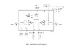
I made my first circuit the other day. It is with a TDA1517. All parts were salvaged from the garbage. I was just looking up datasheets as I took things apart until I found something to build. The circuit is the one provided on the chip's data sheet. This is my first "real" circuit ever. I was really happy when I turned it on and it worked -- especially because it was all made from garbage.

Now, I want to ask a question about something. I know about speakers and music and I build my own computers, and play around with ESP32s and other dev boards hooking up sensors and programming, etc. What I don't know are actual "real" circuits (not other peoples' circuits plugged into other peoples' circuits). That said, I want to get a little more power out of this amp. Just a tiny bit more so I can here it where I live (in Salvador, Brazil, in the city, a block from the beach).

The power source is already sorted out according to the datasheet. The speakers I used vary from 2 ohm to 8 ohm and changing things here isn't going to do it.

Someone suggested to get another, identical chip and run both in bridged mode. That is a great idea, but I found this chip in the garbage and I doubt I will find another. Ordering a new chip defeats the whole purpose of this project also (why not order everything I want then?).

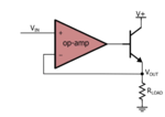
So, is it possible to add power resisters to this circuit? I have a lot of transistors of all kinds from salvage. If so, what kind of circuit would that look like? Would it need its own separate power source?

I don't want to give up. This is fun for me, not a job.

Thanks for any help! amp1.jpg
 

You don't show a schematic, just a picture of a bunch of garbage (as you said)-that's of no help. But, you could perhaps add a transistor on the output of the opamp to boost power. This is the simplest thing you could do, but it may have too much distortion. There are more complex circuits you could investigate.
 

Attachments

  • opamp curent booster.PNG
    opamp curent booster.PNG
    103.2 KB · Views: 157
Last edited:

I said I built it according to the datasheet.

Here is the circuit from the datasheet -- I attached it.

The "garbage" comment was a good one. The difference is, I built the circuit, not the garbage. Thanks bro.
 

Attachments

  • TDA1517.jpg
    TDA1517.jpg
    118.4 KB · Views: 196

Ah, I didn't even realize this was a power amp, I just figured you were using an opamp. You COULD add some external power transistors (you said power resistors, but I assume you mean transistors), but that kind defeats the purpose of having a 6 watt amplifier-you don't need that kind of power to drive an external power stage. Unless you're looking for kilowatts of output power.
 

Hi,

The power of an amplifier could be limited by current or by voltage.
Only if the TDA power is limited by current, then an additional transistor can bring an improvement.

Klaus
 

I made my first circuit the other day.

Congratulations! You want to make lots of noise? You can add a power driver to each of the channels and get a bigger power supply and bigger speakers.
 

You can make Simple Audio Amplifier Circuit for mobile or laptop using Single Mosfet or Single transistor . circuit diagram of very simple and Powerful Audio Amplifier For Listen the Audio from any Mobile or Laptop. The construction of this small Audio Amplifier is very Easy and this is very simple. Use heat sink with Mosfet. This circuit Works Well with 6-9 v supply.
audio amplifier circuit.jpg
For More amplifier circuit
 

Your schematic does not show your supply voltage. The datasheet for the TDA1517 shows a 14.4V supply and an output of only 5W into 4 ohms per channel. The datasheet does not show and does not recommend a higher supply voltage or the reduced power into an 8 ohm speaker. With a 14.4V supply a 2 ohm speaker will overload it and might blow it up.
Use an amplifier with a higher output power that probably uses a higher supply voltage or it has two amplifiers in a bridged mode.
 

Congratulations! You want to make lots of noise? You can add a power driver to each of the channels and get a bigger power supply and bigger speakers.

I don't want to go crazy, but the theory of this is what I was thinking. I just don't know how to do it.

- - - Updated - - -

You can make Simple Audio Amplifier Circuit for mobile or laptop using Single Mosfet or Single transistor . circuit diagram of very simple and Powerful Audio Amplifier For Listen the Audio from any Mobile or Laptop. The construction of this small Audio Amplifier is very Easy and this is very simple. Use heat sink with Mosfet. This circuit Works Well with 6-9 v supply.
View attachment 149602
For More amplifier circuit

Yes, I think this will do it. I can just add this on to what I have. THANK YOU! I didn't know if it was possible, or if it would work making decent results -- not just a ton of distortion.

Other guys, I agree with all that. I stop here with this project after I finish putting it in a box. Really, this little project got me very interested into making me want to go further. I finally feel I understand what is going on -- something finally clicked. I am going to make a LM3886 "gainclone" amplifier. I had no idea what that was a few days ago. I was looking up different chips for audio and that LM3886 seems to be really popular. So, there will be lots of resources for me to look at. Also, I looked at a bunch of pics and YT videos and these builds all look really cool (mostly).

Thanks Everyone!

- - - Updated - - -

Congratulations! You want to make lots of noise? You can add a power driver to each of the channels and get a bigger power supply and bigger speakers.

Thank you for the congratulations! I was waiting for that from someone, anyone... LOL My wife just said, "oh" "um" "cool?".
 

Hi,

Power means voltage and current.
Voltage without current is no power...current without voktage is no power, too.

A speaker has a nominal impedance - it will vary with frequency - but you can calculate with it.

Example:
Let's say you have a speaker with 4Ohms...and the amplifier is able to drive 12V peak output.
If the amplifier can drive 100mA only ... then the peak power is limited to I × I × R ... which is 40mW peak only.
Due to current limitation the output voltage will be limited to I × R = 400mV peak.

According Ohm's law a load with 4Ohms will draw 3A from 12V.
Thus this amplifier needs to be able to drive 3A...then you get a peak power of 36W.

But if the same amplifier is able to drive 10A, then the peak output power won't increase, because it is limited by the 12V voltage.

In short: For a high power amplifier you need high voltage as well as high current.

Klaus

So, if I add the amplifier circuit circuitspedia posted above (one for each speaker output), I would power those two circuits separately (like I think it shows)? I am still not quite sure how that circuit works with what I have.

At this point, I think I am going to leave this circuit alone. It could be a little louder, but it is ok. It was an awesome learning experience. I want to understand better how the amplifier circuit circuitspedia posted above adds on to something. I also want to understand this power theory better. I need a simple circuit to build an unregulated power supply around 16VDC +/- and also start playing around changing speakers and amp chips. For fun.

Thanks.
 

The circuitspedia amplifier in post #7 is completely wrong because its output power is very low and it puts DC in the speaker which causes its cone to be always near one side and cause damage and/or distortion.

- - - Updated - - -

Example:
Let's say you have a speaker with 4 Ohms...and the amplifier is able to drive 12V peak output.
An amplifier powered from 12V will have a peak output of about 3W into 4 ohms (TDA2009). Its peak output is about 4.9V, not 12V, because its output idles at half the supply voltage which is 6V and its output has a voltage loss of about 2.2V peak to peak.

According Ohm's law a load with 4 Ohms will draw 3A from 12V.
Thus this amplifier needs to be able to drive 3A...then you get a peak power of 36W.
No. The peak voltage in 4 ohms with a 12V supply is only 4.9V then Ohm's Law calculates the peak output current to be 4.9V/4 ohms= 1.23A.

There is no such thing as peak power, it is simply the real sinewave power doubled, then the sinewave output cannot be 36W/2= 18W, instead it is only 3W.
 

I need a simple circuit to build an unregulated power supply around 16VDC +/-

Example of class B amplifier. Half-bridge.
Bipolar supply +-16V. Load is 2 ohms.

The incoming signal provides the bias current which drives the transistors. Output amplitude depends directly on input amplitude. So you might want to increase voltage of a soft signal by running it through a pre-amp (possibly class A).

The simulation has 60-70 W going to the 2 ohm speaker. At these power levels it generates lots of heat because the transistors are operated in resistive (linear) mode. Nevertheless class B is more efficient than the class A amplifier.

class B 16VAC sine input +-16V supply load 2 ohms.png

You can see crossover (or null) distortion near the 0V centerline. This is known as an undesirable characteristic of class B. It's noticeable at soft volume, which reduces its appeal among hi-fi purists. Nevertheless class B is simple and easy to understand. By adding a few more components you can turn it into class AB which has less distortion and is popular to use for the output stage.
 

There is no such thing as peak power, it is simply the real sinewave power doubled,

Can you please explain this in simple English? This sounds Greek or Hebrew (no offence intended) to me. I understand each word individually but I cannot get what is the intended meaning...
 

Hi,

@audioguru:

I know you have much experience with real audio circuits. ... and I know what you mean... but you need to read carefully what I have written:
Example:
Let's say you have a speaker with 4 Ohms...and the amplifier is able to drive 12V peak output.
While I clearly talk about output voltage you talk about supply voltage.
For sure an amplifier that is able to drive 12V output needs higher supply voltage.
But I tried not to confuse the OP with
* voltage drop on transistors,
* RMS values
* distortion
* damping factor
... and all the other stuff you need when you want to build a good audio amplifier.
I didn't want to talk about unipolar power supply, bipolar power supply, amplifiers with or without series capacitors at it's output, bridge configuration....and how all this influences an amplifier's output voltage...

I just tried to tell him that Ohm's law is essential to calculate the relationship between voltage and current.
... Although I know that no speaker is pure ohmic load....

Klaus
 

Can you please explain this in simple English? This sounds Greek or Hebrew (no offence intended) to me. I understand each word individually but I cannot get what is the intended meaning...
Many cheap amplifiers are advertised saying "peak" power or "maximum" power which simply doubles the real sinewave power. The real sinewave power has a sinewave at the output with the RMS voltage level as high as it can go without clipping. Peak power is simply double that since the voltage peak is 1.414 times (the root of 2) higher and then the current is also the root of 2 times higher. 1.414 x 1.414=2.
Then the advertisers turn up the volume so that the output is a severely distorted squarewave that sounds awful but also makes the power number higher.
 

Peak power is peak sinewave power, anything else is meaningless. By your method you could just drive a maximum D.C. Level out of the amp and call that peak power. But to say "there is no such thing as peak power" is misleading and confusing to the OP who is just learning.
 

Status
Not open for further replies.

Part and Inventory Search

Welcome to EDABoard.com

Sponsor

Back
Top