neazoi
Advanced Member level 6
Hi, I have opened in the past this thread
https://www.edaboard.com/showthread...overnight-AAA-Ni-MH-charger&highlight=charger
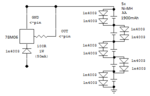
I want to do the same but for 5 x AA Ni-MH batteries
Can you please suggest me if this can be done with batteries in series and what changes do I need to do to the charger circuit?
The previous schematic is here **broken link removed** near the middle of the page
https://www.edaboard.com/showthread...overnight-AAA-Ni-MH-charger&highlight=charger
I want to do the same but for 5 x AA Ni-MH batteries
Can you please suggest me if this can be done with batteries in series and what changes do I need to do to the charger circuit?
The previous schematic is here **broken link removed** near the middle of the page
")