Continue to Site

Welcome to EDAboard.com

Welcome to our site! EDAboard.com is an international Electronics Discussion Forum focused on EDA software, circuits, schematics, books, theory, papers, asic, pld, 8051, DSP, Network, RF, Analog Design, PCB, Service Manuals... and a whole lot more! To participate you need to register. Registration is free. Click here to register now.

How to choose a suitable sampling frequency for this current sensor?

Status
Not open for further replies.

Xavier Pacheco Paulino

Junior Member level 1
Joined
Nov 8, 2015
Messages
18
Helped
0
Reputation
0
Reaction score
0
Trophy points
1
Activity points
188
I'm using this current sensor TLI4970-D050T4 located at the emitter leg of a power IGBT. This transistor is being switched at 10 kHz. How do I choose the convenient sampling frequency for the sensor? My bandwidth is 18 kHz. The IGBT is used in low side switching application to control a DC motor. How fast should I sample the current to get valuable information?
 

The question is partly unclear without knowing the current waveform. Measuring the switch current of a 10 kHz pwm system with 18 kHz bandwidth sounds questionable in any case. It probably would make more sense to measure the motor current which can be expected continuous in a first order.

How's the measurement used in the control system?
 

I'm learning how to use this sensor. So, I appreciate any guidance. The sensor is physically located at the emitter leg of the IGBT as said before. So, what useful information about the current can I obtain with this sensor and how? The sensor has overcurrent detection. I'm using this feature through an interrupt routine as pointed out in the datasheet. But, how can I get the actual motor's current? I mean, my original question was about how fast I should sample the current so I get useful information. For example, I was sampling every 10 ms, but someone told me it's too slow.
 

The circuit topology isn't completely clear, I presume it's some kind of buck converter. If you want the motor current, you'll measure the motor current, not the switch current.
Because the switch current is pulsed, any sampling method that is not synchronized with the PWM will produce an aliasing error.
 

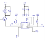
This the circuit:

TLI.PNG
 

That's what I expected. It's a buck converter with the motor inductance used as storage inductor. IGBT and D5 current are pulsed, motor current is more or less continuous. Why don't you place the current sensor in series with the motor?
 

I thought of that after I got my PCB. Now, physically the current sensor is in the emitter leg. Unfortunately, I have to use it like that for now. For a future design, I will consider placing it in series with the motor. So, how fast would you sample the current in that circuit?
 

For example, I was sampling every 10 ms, but someone told me it's too slow.

By measuring average Ampere draw you can get an approximate idea of motor speed, Calculate the average of a hundred readings per second, or ten or 1 per second. It's approximate because the load is another factor which influences rpm, and applied voltage also influences rpm.

With an RC network you can smooth the waveform, allowing you to take an average reading of your sensor.

If you want to read accurate motor speed, then you must make exact count of cycles going through the motor, and divide by number of windings (brush contacts) inside motor.
 

Hi,

By measuring average Ampere draw you can get an approximate idea of motor speed,
I don't agree.
The average motor current is a measure of torque, not if speed.
But here we even can't say average motor current, because it depends on duty cycle, load behaviour, CCM vs DCM through freewheel diode.
There is a much better relationship between duty_cycle and RPM than average_switch_current and RPM.

I've done some tests in the past and found out that for a motor (complex load) with variable load there is no good relationship between
average_switch_current and average_motor_current, because there are too much unknown parameters.

But the setup is good to protect the transistor against overcurrent, but then one should use a fast reacting comparator, no averaging and ADC.

Maybe the OP is satisfied with the average switch current.
Then keep on nyquist: first decide the sampling frequency that is useful for your application, then calculate a useful anti aliasing filter.

Klaus
 
I would proceed as follows:
- configure the low-pass filter so that pwm pulses are sufficiently averaged, e.g. 1 kHz or below
- choose a sampling rate according to the expectable current change speed
- estimate motor current from average switch current and pwm duty cycle
 

I guess I ought to clarify my earlier remark:
By measuring average Ampere draw you can get an approximate idea of motor speed.

It is common to see Ampere draw go up when motor speed goes down (or stalls). A free-running motor draws less current. The reason has to do with how much time a motor winding spends connected to power. I was referring to this simplified theoretical relationship. It's an inverse relationship.

However as Klaus points out (post #9), the relationship is affected when we add unknown parameters such as load behavior, variable voltage, PWM, etc.
 

Status
Not open for further replies.

Part and Inventory Search

Welcome to EDABoard.com

Sponsor

Back
Top