Continue to Site

Welcome to EDAboard.com

Welcome to our site! EDAboard.com is an international Electronics Discussion Forum focused on EDA software, circuits, schematics, books, theory, papers, asic, pld, 8051, DSP, Network, RF, Analog Design, PCB, Service Manuals... and a whole lot more! To participate you need to register. Registration is free. Click here to register now.

Tuning range of an LC VCO

Status
Not open for further replies.

hanen88

Member level 1
Joined
Sep 29, 2014
Messages
39
Helped
0
Reputation
0
Reaction score
0
Trophy points
1,286
Activity points
1,630
Hi,
I asked how can i display the output frequency of an LC VCO versus control Voltage of its varactor. If you have a tutorial which can help me.
I'm so grateful to help me.
Sincerly
 

Do a HB analysis with a sweeping variable ( Vtune ) then plot freq. vs. Vtune.
You can do it in ADS or Cadence SpectreRF..
 

Thank you, i use ADS in simulation, however i need a clear tutorial which specify all parameter and equation. I'm so grateful to send me tutorial in ADS how to display tuning rang of a differential LC VCO .
 

Thank you, i use ADS in simulation, however i need a clear tutorial which specify all parameter and equation. I'm so grateful to send me tutorial in ADS how to display tuning rang of a differential LC VCO .

You can also use "Oscillator Design Guide" in ADS.there are many "templates" for such kind of simulations.It's really simple.
You will create a OSC testbench, you define your variables in HB controller then run the simulator.
I don't think there are particular tutorials for your target.( Maybe there is but I don't know )

I used tuned frequency oscillator and frequency pushing. I define first my oscillator as a symbol and i define the ouput terminal, however i don't know where is the input terminal. Can ou help me to specify the input node. After that, i should specify the control voltage as a terminal which will be sweeped after. Thank you for you hell
 

You have a VCO with 2 port.
One Port is the Output and other one should be the Vtune Input.
The Output is connected to a Load, Vtune is connected to a variable DC Voltage Source.
All you have to do to sweep this DC Voltage from lowest value to highest value and observe the VCO Frequency.
That's it..
 
Thank you, i replace the oscport by my test bench circuit and i connect the output to the load and the control voltage to the input terminal. However, when i simulate, an error is generated'No component named oscport1was found when lookin for oscport'. Knowing that i called my circuit oscport1 but it doesn't know my device. What can i do to correct this error.
 

Post you simulation schematic here..And HB Controller-Oscillator Settings capture
 

There are the shematic and the error. What can i do to simulate correctly this template
Tuning range.png
error.png
 

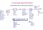
I think you set-up has some errors.It should look like
osc_vco.jpg
Delete your set-up (ans sub-circuits) and re-create it. If the problem persists, check your library/design guide installation because when you call "Voltage Controlled Oscillator-->>Tuned Frequency oscillator" template, ADS has to create automatically this template.Otherwise there is an installation or license problem.
But first of all, Read-please-carefully Oscillator Design Guide part of ADS help.Because there are many option and choices and find the optimum one for your application.
 

Status
Not open for further replies.

Part and Inventory Search

Welcome to EDABoard.com

Sponsor

Back
Top