Continue to Site

Welcome to EDAboard.com

Welcome to our site! EDAboard.com is an international Electronics Discussion Forum focused on EDA software, circuits, schematics, books, theory, papers, asic, pld, 8051, DSP, Network, RF, Analog Design, PCB, Service Manuals... and a whole lot more! To participate you need to register. Registration is free. Click here to register now.

FM signal demodulating

Status
Not open for further replies.

000SHREDDER000

Full Member level 1
Joined
Apr 9, 2017
Messages
96
Helped
0
Reputation
0
Reaction score
0
Trophy points
6
Activity points
676
Hi all, I have a new question again:-D, FM demodulator output singnal is in the audio frequency range or not?
FM2.PNG
 

Hi,

"The SI unit of audio frequency is the hertz (Hz). It is the property of sound that most determines pitch. The generally accepted standard range of audible frequencies for humans is 20 to 20,000 Hz, although the range of frequencies individuals hear is greatly influenced by environmental factors." Wikipedia
 

You can run a Fourier analysis to check this by yourself; for an audio signal one would expect a flat transfer input/output ratio at the frequency range above mentioned.
 
You can run a Fourier analysis to check this by yourself; for an audio signal one would expect a flat transfer input/output ratio at the frequency range above mentioned.

I can see it's not, I know the circuit is correct isn't it? it's a simple FM demodulator, how can I extract audio from it then?
 

Ok, if you insist on a short answer:
Yes, you are already getting an audio output.

Then why I see the same frequency in the input and output always, If I can use this shape of wave as a audio like AM so I can use it, but problem is frequency,
in that frequency I cant use audio amps like LM386 because it can't work above 1mhz, but I saw many people used it for FM signal amplifying.
 
Last edited:

First of all you did not specify from where you are probing the output signal. Secondly, you are injecting a carrier signal from a frequency perhaps quite below the resonance of the tank (right now I'm too lazy to make the calculation for you - 1/√LC). Third, your scope has no information about the Y-axis nor whether the input signal is shifted from zero or not, which means the the above circuit is likely just doing what is expected - let pass to output values above diode voltage drop and/or considering parasitics instead of rectifying. As a side note I would recomment next time you take time to draw the (simple) circuit a few more readable
 
  • Like
Reactions: 000SHREDDER000

    V

    Points: 2
    Helpful Answer Positive Rating

    000SHREDDER000

    Points: 2
    Helpful Answer Positive Rating
thank u for your accurate answers.
I have a 3 questions.
1 So I can only calculate for a single frequency output, how it can work for all FM band?
2 In the common FM slope detector circuit we have 2 tanks, resonance of first tank is different form second one or they have same resonance?
3 can we design an FM/AM demodulator?
 

can we design an FM/AM demodulator?
Your questions are too broad, and it is not expected that you will learn from the answers got here. As said in another thread, you need to understando the fundamentals before doing something. A common FM and AM receviver has also the intermediary frequency at some stage, which turns easiest the tunning process. Your circuit is nothing else than containing part of the whole, not a demodulator as you claim, therefore instead of doing so, I would recommend you start with a known complete circuit took from somewhere and then inspecting its working at each point.
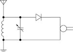
 
Your questions are too broad, and it is not expected that you will learn from the answers got here. As said in another thread, you need to understando the fundamentals before doing something. A common FM and AM receviver has also the intermediary frequency at some stage, which turns easiest the tunning process. Your circuit is nothing else than cantaining part of the whole, not a demodulator as you claim, therefore instead of ding so, I would recommend you start with a known complete circuit took from somewhere and then inspecting its working at each point.

Thank you for your helpful answers.
You know I have a big issue, I can't understand how an AM demodulator works, If you put a diode front of LC for demodulating AM only you can cut half of the wave then you didn't turn carrier frequency to the audio frequency?
Then how you can hear audio?


309900.image0.jpg
 

The earphone/headphone/loudspeaker cannot respond to high frequencies so to some degree it works like a low pass filter already but a proper LPF will give more consistent and reliable results. At the very least a capacitor should be connected across the load to remove residual carrier.

The point about the diode is that without it, the average signal level is zero because it consists of equal positive and negative voltages. When rectified so only one polarity is recovered, it gives a voltage proportional to the signal amplitude - and that is the AM you want to recover.

Brian.
 

that's what I want to know, maybe crystal earpiece acts like a Low pass filter.
 
Last edited:

Why LPF cap is behind of Q1?
Can i move it front of Q1, because 2n4401 can't work above ~ 250 Mhz?

pp.PNG
 

The 2N4401 specification has nothing to do with it. You still haven't explained what the circuit is supposed to do.

It can be used as an AM detector ONLY IF it has a selective filter ahead of it. In that configuration, the transistor works as an audio amplifier and C6 is to prevent the carrier reaching the output stage. If you move C6 to the input it shorts out the signal.

It will also work as an FM discriminator but only if the input signal is large (more than about 1V) and the frequency is very low. In that case, the transistor works as a switch and it tries to keep C6 discharged all the time. A sufficient input voltage will turn the transistor off and allow charge to flow through R5 and R6 so C6 voltage increases. This is called a 'pulse counting discriminator' because the rate of input pulses (frequency) determines how much voltage is allowed to build up across C6. It will only work with low frequencies though, it can't handle more than a few KHz so it has limited use to produce audio out.

Brian.
 
the rate of input pulses (frequency) determines how much voltage is allowed to build up across C6.
Brian.

Can you explain how the rate of input frequency determines amount of voltage?
 

That low pass filter can't demodulate higher frequencies?
 

Can you explain how the rate of input frequency determines amount of voltage?
Imagine you have a capacitor charging through a resistor, the voltage gradually rises until it reaches the supply voltage. Now imagine a switch that connects across the capacitor, each time it closes, the capacitor discharges and its voltage drops to zero.
What you have in your schematic is C6 charging through R5 and R6 making the voltage increase and Q1 working as a switch to discharge it back to zero. The rate it charges and discharges will determine the average voltage across C6. The charging rate is fixed by the resistors but the discharge rate is determined by the input signal. Faster repeating input pulses will discharge C6 more frequently so it's voltage will not have time to rise very much. If the input signal is at a lower frequency, C6 has longer to charge up so it's average voltage will be higher. So it converts frequency to voltage which is what an FM demodulator does. That kind of demodulator only works on low frequencies and isn't very linear so it isn't normally used for audio recovery.
That low pass filter can't demodulate higher frequencies?
Low pass filters are not demodulators! There are some specific cases where a filter can be used to recover a voltage proportional to frequency (slope demodulation) but that isn't how your schematic works.

Brian.
 
What do u think about this one, I hope it's better for higher frequencies?
airecraft.PNG
 

Status
Not open for further replies.

Part and Inventory Search

Welcome to EDABoard.com

Sponsor

Back
Top