Continue to Site

Welcome to EDAboard.com

Welcome to our site! EDAboard.com is an international Electronics Discussion Forum focused on EDA software, circuits, schematics, books, theory, papers, asic, pld, 8051, DSP, Network, RF, Analog Design, PCB, Service Manuals... and a whole lot more! To participate you need to register. Registration is free. Click here to register now.

Unable to draw the correct unit cell in CST using AutoCAD

Status
Not open for further replies.

David19

Newbie level 1
Joined
Oct 10, 2018
Messages
1
Helped
0
Reputation
0
Reaction score
0
Trophy points
1
Activity points
11
Dear All, I am currently doing a project that requires me to use both CST and AutoCAD. Please refer to the screen shots below for the models that I have drawn in AutoCAD before exporting it to CST. The entire patch is solid which is not what I want. What I need is a gap in between the patch and the outer ring as shown in the picture below. I am unable to edit the structure in CST. Please advice on what I should do on the AutoCAD side to correct the error. Thank you

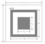
cst.JPGcell.JPGautocad.JPG
 

Have you tried using Boolean operation to subtract from the square with L1 sides? I find CST workspace is quite easy to draft the unit cell and I can export into AutoCAD and duplicate more if I need to.
 

you can change the material of those part into vacuum as well.
 

Status
Not open for further replies.

Part and Inventory Search

Welcome to EDABoard.com

Sponsor

Back
Top