doncarlosalbatros
Full Member level 2
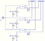
I need to control multiple AC mains power terminals which are going to power DC power supplies. The aim of the control is just to switch OFF or ON the power for the DC power supplies when needed(not a nonstop ON OFF). So basically the idea is cut their electricity by a microcontroller board such as Arduino board's digital outputs. Total number can be around six but for simplicity I drew a diagram for three:

In the above diagram D1, D2, D3 are microcontroller 0/5V digital outputs. Q1, Q2 and Q3 are transistors to not to load the digital pinouts. SSR1, SSR2 and SSR3 are solid state relays which control the line terminal for the AC power entry to galvanically isolated power supply units PSU1, PSU2, and PSU3 individually.
So for the moment, I ended up with this SSR for the purpose. Another one is this.
But before I have couple of hesitations and questions:
1.) As in the diagram the SSRs in my case will turn ON or OFF the DC power supplies. So I don't have any motor or inductive type of load it seems. But these SSRs has mainly two switching types: Zero-cross and Random. Would a random SSR work fine for this application? If I use zero-cross type would it have any bad effect for this type of scenario?
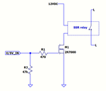
2.) Is my way of using the transistors(not to load the digital pins) correct? There is not input impedance of the SSR input given in its datasheet. So I wonder would the transistor need any resistor across(100k in my diagram) or in parallel?
(In another form someone wrote that EMI can be a problem through signal path and high impedance)
I'm really in need to make this work properly.
