Siva12357
Newbie level 1
Hi,
Setup:
I am using OPA549 opamp IC to drive a coil of inductance of about 200 mH (burst sine pulses of 60Vpp of 90KHZ frequency and repetition rate of 1KHZ and 10 cycles per burst.
The OPA549 is used in unity gain configuration and a cap is added in series before the coil to limit DC current going to the coil..

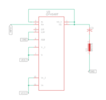
The above pic shows the schematics of the design... In addition to this a 10uF ceramic capacitor was added in layout of the PCB near the power pins..
The IC for now has no Heat sink as it is operating only in burst mode..
Problems Faced:
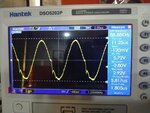
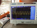
Now Coming to the problems I am facing. The output of the opamp with no load is perfect without any distortions. But as soon as I connect a load (resistive or Inductive) there is a wierd distortion in the negative side of the output the positive side still remains distortion free. Pictures attached below.
with 1 ohm load 6Vpp Output signal

with coil of 200mH inductance (probe settings wrong on scope)

Tried out solutions:
Adding more decoupling caps - Not much change in distortions but still noticable change.
Reduced the frequency of the burst - No change.
Other experimantal conditions:
Two single supply power supplies where used to power the opamp (negative of PS1 connected to positive of PS2 and positive to PS1 connected to VCC and negative of PS2 connected to VEE)
Current limit of each powersupply is 5 amps. VCC at 30V and VEE at -30V.
Can someone please help me troubleshoot why there is distortion.. Thanks in advance
Setup:
I am using OPA549 opamp IC to drive a coil of inductance of about 200 mH (burst sine pulses of 60Vpp of 90KHZ frequency and repetition rate of 1KHZ and 10 cycles per burst.
The OPA549 is used in unity gain configuration and a cap is added in series before the coil to limit DC current going to the coil..

The above pic shows the schematics of the design... In addition to this a 10uF ceramic capacitor was added in layout of the PCB near the power pins..
The IC for now has no Heat sink as it is operating only in burst mode..
Problems Faced:
Now Coming to the problems I am facing. The output of the opamp with no load is perfect without any distortions. But as soon as I connect a load (resistive or Inductive) there is a wierd distortion in the negative side of the output the positive side still remains distortion free. Pictures attached below.
with 1 ohm load 6Vpp Output signal

with coil of 200mH inductance (probe settings wrong on scope)

Tried out solutions:
Adding more decoupling caps - Not much change in distortions but still noticable change.
Reduced the frequency of the burst - No change.
Other experimantal conditions:
Two single supply power supplies where used to power the opamp (negative of PS1 connected to positive of PS2 and positive to PS1 connected to VCC and negative of PS2 connected to VEE)
Current limit of each powersupply is 5 amps. VCC at 30V and VEE at -30V.
Can someone please help me troubleshoot why there is distortion.. Thanks in advance