Continue to Site

Welcome to EDAboard.com

Welcome to our site! EDAboard.com is an international Electronics Discussion Forum focused on EDA software, circuits, schematics, books, theory, papers, asic, pld, 8051, DSP, Network, RF, Analog Design, PCB, Service Manuals... and a whole lot more! To participate you need to register. Registration is free. Click here to register now.

THD using pss analysis for a fully differential amplifier

Status
Not open for further replies.

ICdesignerbeginner

Member level 5
Joined
Nov 22, 2017
Messages
86
Helped
1
Reputation
4
Reaction score
2
Trophy points
8
Activity points
729
I want to find the THD of fully differential amplifier. I am using cadence virtuoso. I have found three options in simulating the THD in cadence which are:

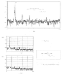
1. using PSS analysis---- I select pss analysis then got ---direct plot --- forum forum then select voltage--- I place no. of harmonics i.e. 10 (I have kept)---fundamental frequency---select net as--differential and then select the two output nodes of my differential amplifier---It shows it in the form of 10 vertical straight lines because I have set the no. of harmonic as 10. I am taking the difference between the first harmonic and third harmonic which shows 58 dB.

2. Second option is I am doing transient analysis. On this transient response of the fully differential output I apply DFT fusing calculator and then take 20 dB---- I again get vertical lines as harmonics this time I get 53 dB which is the difference between first and third harmonic.

3. Third option is I have done transient analysis----apply THD using calculator ---take 20 dB--- This time it doesn't show waveform, it shows in form of numbers -10 dB, which I think is wrong.

I havent placed any port in my circuit The only source is the input sources of differential amplifiers. Which one is correct? Can anyone help.

i ALSO want to calculate SNR. There is no SNR option in calculator? Anyother way to find SNR?
 
Last edited:
  • Like
Reactions: shadow222

    shadow222

    Points: 2
    Very useful question, especially since the author also posted several possible solutions.
Can you understand a definition of THD, SNR, SINAD ?
THD is not ratio of funadmental-component and 3rd-order-harmonic.

Don't rely on Direct Plot Form in Cadence ADE blindly.
Use skill functions directly with understanding THD definition surely.

1. using PSS analysis
............................................
It shows it in the form of 10 vertical straight lines because I have set the no. of harmonic as 10.
I am taking the difference between the first harmonic and third harmonic which shows 58 dB.
If you use Shooting-Newton-PSS, no. of harmonic as 10 is enough.
However, if you use HB-PSS, it is too few.

2. Second option is I am doing transient analysis.
On this transient response of the fully differential output I apply DFT fusing calculator
............................................
I again get vertical lines as harmonics this time I get 53 dB which is the difference between first and third harmonic.

3. Third option is I have done transient analysis
----apply THD using calculator ---take 20 dB---
This time it doesn't show waveform, it shows in form of numbers -10 dB, which I think is wrong.
Don't use function without understanding its definition.

"thd()" returns value as "%".

So 20*log10(10**(-10/20)/100)=-50dB

I havent placed any port in my circuit
Why do you require "port" ?

The only source is the input sources of differential amplifiers.
Do you surely set common mode bias ?
Can you understand the followings ?

There are two modes regarding input drive, common mode and differential mode.

Also there are two modes regarding output, common mode and differential mode.

Which one is correct?
Any of three could be correct, as far as you can understand THD correctly and you can do simulation correctly.

i ALSO want to calculate SNR.
There is no SNR option in calculator?
Anyother way to find SNR?
Simply calculate SNR based on its definition.

Here noise power can be evaluated by PSS/Pnoise.
Distortion's power can be evaluated by PSS.

If you would like to use Transient Analysis, you have to use Transient-Noise Analysis.

Noise power which is evaluated by conventional Transient Analysis is no more than numerical noise not physical noise.
 

Attachments

  • 180928-195534.png
    180928-195534.png
    66 KB · Views: 191
Last edited:

Can you understand a definition of THD, SNR, SINAD ?
THD is not ratio of funadmental-component and 3rd-order-harmonic.

I am not taking ratio I am taking difference between first and third harmonic. I have seen paper showing difference between third and first harmonic.

Don't rely on Direct Plot Form in Cadence ADE blindly.
Use skill functions directly with understanding THD definition surely.

If you use Shooting-Newton-PSS, no. of harmonic as 10 is enough.
However, if you use HB-PSS, it is too few.

In cadence version which I am using dosent have shooting-Newton and HB-PSS option so I am just using PSS analysis


Don't use function without understanding its definition.

"thd()" returns value as "%".

So 20*log10(10**(-10/20)/100)=-50dB

Using calculator THD gives in % but I have taken 20 log with it so its in dB. and thats coming as -10
Please correct me if I am wrong.

Why do you require "port" ?

Do you surely set common mode bias ?
Can you understand the followings ?

There are two modes regarding input drive, common mode and differential mode.

Also there are two modes regarding output, common mode and differential mode.

yes I have placed the common mode and differential mode.

Any of three could be correct, as far as you can understand THD correctly and you can do simulation correctly.

Simply calculate SNR based on its definition.

Here noise power can be evaluated by PSS/Pnoise.
Distortion's power can be evaluated by PSS.

If you would like to use Transient Analysis, you have to use Transient-Noise Analysis.

Noise power which is evaluated by conventional Transient Analysis is no more than numerical noise not physical noise.
How can I use Distortion power can you help me in This? I want to calculate input referred noise?

To get SNR , I divide my input signal with noise power/input referred noise and get SNR?

Is this noise power and spectral noise density the same?

what does this 0_waveform/n_thd/nil means? what is /nil?
 
Last edited:

Post thread after learning very basic things surely.

I am not taking ratio I am taking difference between first and third harmonic.
You can not undetstand very basic thing at all.

Difference of dB value is ratio of linear value.

Again, can you understand THD surely ?
https://www.edaboard.com/showthread.php?376046

I have seen paper showing difference between third and first harmonic.
Surely see "paper".

In cadence version which I am using dosent have shooting-Newton and HB-PSS option so I am just using PSS analysis
No, you can not understand anything at all.
Surely see GUI of PSS.
Or see "spectre -h pss".

Using calculator THD gives in % but I have taken 20 log with it so its in dB. and thats coming as -10
Please correct me if I am wrong.
Are you kindergarten pupil ?
Surely see my append.

How can I use Distortion power can you help me in This?
If you don't include higher order harmonic distortion as noise, you don't evaluate higher order harmonic distortion power.
SNR is defined without distortion in attached figure.

Simply, S/N or S/(N+D).

I want to calculate input referred noise?
I can not understand what you want to mean at all.

To get SNR , I divide my input signal with noise power/input referred noise and get SNR?
No.
However your input level is linear opeartion region, it is close to true SNR.

Is this noise power and spectral noise density the same?
No.
 

Attachments

  • 180928-210304.png
    180928-210304.png
    43.8 KB · Views: 154
Last edited:

Status
Not open for further replies.

Similar threads

Part and Inventory Search

Welcome to EDABoard.com

Sponsor

Back
Top