Continue to Site

Welcome to EDAboard.com

Welcome to our site! EDAboard.com is an international Electronics Discussion Forum focused on EDA software, circuits, schematics, books, theory, papers, asic, pld, 8051, DSP, Network, RF, Analog Design, PCB, Service Manuals... and a whole lot more! To participate you need to register. Registration is free. Click here to register now.

[SOLVED] increase LED operating duration

Status
Not open for further replies.

Zak28

Advanced Member level 2
Joined
Aug 19, 2016
Messages
579
Helped
6
Reputation
12
Reaction score
6
Trophy points
18
Activity points
4,681
I have a circuit were a LED blinks for ~10mS every few seconds as its attached to the output of an oscillator which triggers a transistor to further operate the circuit and that LED is supposed to be an indicator for circuit operation. Is there a simple method to increase the LED firing duration? The 10mS duration is far too short. I would like something simple.

Thank you.
 

If you post the schematic then we can tell you which capacitor or resistor to change in the oscillator.

The LED should fire for much longer durations. The pulse duration is ~10mS which is too short for a LED as an indicator.

Screenshot_20180927_190412.png

View attachment IGBT-Gate-Drive-555.zip
 
Last edited:

  • Like
Reactions: Zak28

    Zak28

    Points: 2
    Helpful Answer Positive Rating
Hi,

That's confusing.
You want to increase the 10ms timing, but you don't want to modify the duty cycle.
Then the only chance is to reduce the frequency.

The circuit already shows which resistor is responsible for the frequency. Use a higher value.

Klaus
 
  • Like
Reactions: Zak28

    Zak28

    Points: 2
    Helpful Answer Positive Rating
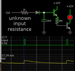
Simple pulse extender made from discrete components. Incoming pulses charge the capacitor. In turn the capacitor provides bias for the transistors. The darlington arrangement increases sensitivity, allowing you to have a smaller capacitor.

pulse extender diode cap darlington NPN's led.png

A logic gate can be used instead of transistors.
 
  • Like
Reactions: Zak28

    Zak28

    Points: 2
    Helpful Answer Positive Rating
Hi,

A solution with more parts than Brad's nice solution (bonus!) would be to make the "high" output blip low/inverted and trigger a monostable 555 with it, i.e. put an inverting NPN at the output and connect a second 555 as a monostable to divide down the frequency/make the LED be on for longer. The benefit would be a neater squarewave output, if that were a requirement. The 18V/225mA is pointing out the absolute maximum ratings and not recommended operating conditions of 16V/200mA for the NE555 I suppose, the SE555 can be run at 18V but only 200mA.
 
  • Like
Reactions: Zak28

    Zak28

    Points: 2
    Helpful Answer Positive Rating
Hello,
If you want to excess the LED service time, you should know how to protect the LED lighting circuit firstly, you can check this link https://www.apogeeweb.net/article/29.html. Hoping it can help you to deal with your problem.
 

The pulse duration is ~10mS which is too short for a LED as an indicator.
Disagree in principle. Perceived intensity of short flashes < 50 ms is proportional to ∫Idt. Instead of increasing the duration, you can increase the LED current. I have designed low power LED indicators with e.g. 2 ms pulse duration. You surely want to use high intensity LEDs.
 

All flashes (shorter then the persistence of vision; about 100 ms) will appear to be stretched to about 100 ms. So if the pulse duration is 10 ms, it will appear to be 100 ms to the naked eye. But the intensity will suffer (PWM effect)- you will see the total energy output per pulse as the app intensity.

But you cannot (and should not) increase the current to compensate for the loss of brightness. The LED may not be able to take a huge pulse. Perhaps for 20mA you can use 200mA for a 10 ms/s pulse but there will be a limit.

But I have not followed the original objective; do you find the brightness too little? Perhaps a small cap can be used to stretch the pulse (but this works only a little).
 

Hi,

speaking for the LED only (not the driver circuit): DC current gives the best input_energy/brightness ratio.
Thus it´s more effective to use 20mA with 10% duty cycle than 200mA with 1% duty cycle.

Klaus
 
  • Like
Reactions: Zak28

    Zak28

    Points: 2
    Helpful Answer Positive Rating
Thus it´s more effective to use 20mA with 10% duty cycle than 200mA with 1% duty cycle.
Yes, but is the small difference relevant in the present case? The discussion is about adding a dedicated pulse extension circuit to increase the perceived light intensity. My point is you can probably accept 5 or 10 % efficiency reduction if you avoid the circuit overhead?
 
  • Like
Reactions: Zak28

    Zak28

    Points: 2
    Helpful Answer Positive Rating
Simple pulse extender made from discrete components. Incoming pulses charge the capacitor. In turn the capacitor provides bias for the transistors. The darlington arrangement increases sensitivity, allowing you to have a smaller capacitor.

View attachment 149288

A logic gate can be used instead of transistors.

Going with the suggested circuit.

Screenshot_20181007_130506.png
 

Status
Not open for further replies.

Similar threads

Part and Inventory Search

Welcome to EDABoard.com

Sponsor

Back
Top